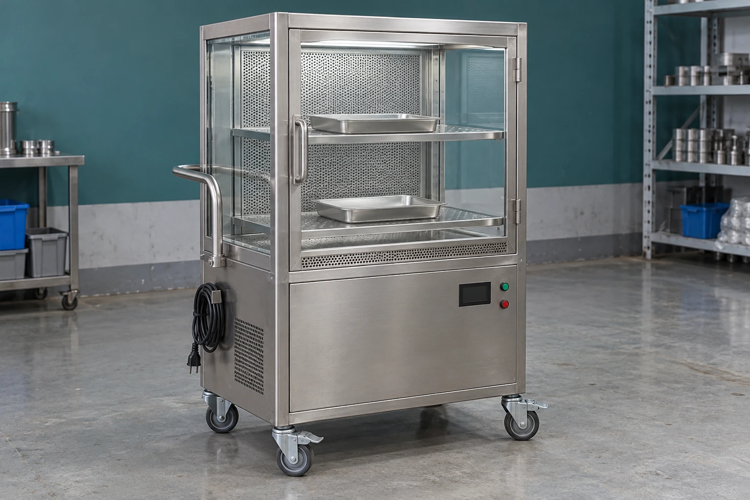
Mobile filtered material transfer
Laminar Flow Carts
| Airflow arrangement | Horizontal or vertical; single-pass or recirculating layout |
|---|---|
| Usable chamber W × D × H (mm) | 600 × 670 × 610; 720 × 1049 × 958; 960 × 1150 × 1280 |
| Chamber construction | Stainless steel; transparent access panels or doors; removable tray supports |
| Filtration | Prefilter with H13 or H14 HEPA filter, selected for the process |
| Power | 220 V, 50 Hz mains option; onboard battery/UPS for travel |
| Handling | Braked swivel casters; tray rails or perforated shelves; optional height adjustment |
| Monitoring | Airflow indication, filter differential pressure and battery status options |
Dimensions above describe the clear internal chamber. Overall footprint, load rating and battery autonomy are specified with the selected trolley layout.
Cart dimensions, airflow layout, loading interfaces and power configuration can be customized to suit your application.
Laminar Flow Carts carry a filtered air zone with the material being moved. A fan, prefilter and HEPA filter supply a controlled stream of air through an enclosed or partly enclosed loading chamber, while onboard power keeps the fan running between connection points. They are useful when cleaned components, precision assemblies or process trays need protection during movement and short holding periods between workstations.
Airflow and the load
Give filtered air a clear path to the product
The useful protection comes from air reaching the exposed surfaces in an orderly direction. A large container placed directly in front of the supply face can leave the items behind it in a disturbed wake. Filling every shelf opening with solid trays can also change the intended flow path. Chamber volume alone therefore does not describe how much material the cart can carry effectively.
Horizontal flow
Air travels from a filter at the rear or side towards the access end. This arrangement can sweep across separated tray levels without an upper shelf sitting directly between the filter and each lower tray. Keep adequate clearance behind the load and avoid placing a tall item upstream of an exposed critical surface.
Vertical flow
Air enters above the working space and moves downwards. It can suit loads that benefit from overhead supply, but shelves and broad horizontal surfaces need particular attention: a solid upper tray can obstruct air to the level below. The load arrangement and return or discharge openings must be considered together.
The transfer cycle
Protection has to continue through the handover
Load at the correct height
A rail or shelf aligned with the receiving machine reduces lifting and helps trays move without tipping. Include tray lips, door hinges and hand clearance in the interface dimensions. Height adjustment is useful where stations differ, provided the chosen mechanism and stability suit the load.
Close and travel
A transparent enclosure helps operators see whether trays have shifted while reducing direct exposure to surrounding movement. It is still a ventilated chamber, not a hermetic package. Openings, door gaps and outlet paths remain part of the airflow design; they should not be improvised with tape or blocked by packaging.
Park without losing airflow
Brakes hold the trolley at the transfer point. Keep its air intake and discharge clear of walls, stored cartons and the receiving equipment. A route with tight turns, floor joints or door thresholds also needs suitable wheels, load restraint and enough manoeuvring room around projecting handles.
Unload into the next protected step
Opening a chamber in an unsuitable location can expose the load at the final moment. Plan the receiving work area, transfer opening and operator movement together. Where material crosses a fixed room boundary, a pass box or transfer chamber may also be needed as part of the room separation.
Size the battery for the entire trip
The operating interval includes loading, waiting for access, movement, unloading and the return to a charging point. Selecting only for the normal travel time leaves little reserve when the destination is occupied. Battery condition, fan setting and filter resistance affect the available operating time, so autonomy should be established for the agreed configuration and duty.
Useful controls make low charge or loss of airflow visible before the load is exposed. Specify what happens during mains disconnection and reconnection, where the charging lead is retained, and what the operator should do if an alarm occurs. A charge display and a fan-running light answer different questions; neither alone proves that the loaded chamber has the required airflow.
Keep performance and cleaning access visible
Removable shelves and accessible corners make routine cleaning easier. The design should also leave service access to the prefilter, fan, battery and final-filter seal without forcing maintenance staff to dismantle unrelated equipment. Cleaning fluid should be kept away from the filter medium and electrical compartments; the selected surface finish and seals need to tolerate the site's cleaning method.
Filter differential pressure is useful for following resistance changes. It does not establish filter integrity or prove the airflow pattern around a real load. For critical transfers, the acceptance scope should address the installed filter, airflow distribution and loaded operating conditions, including the intended access arrangement. An H13 or H14 filter designation alone is not a cleanliness classification for the whole cart.
The product-protection configuration described here is intended for suitable non-hazardous materials. Hazardous powders, vapours or biological agents require a separately engineered containment solution. A mobile filtered chamber does not sterilize its contents or replace the surrounding facility's transfer procedures.
Choose the cart around the material, then the route
A compact tray carrier can be appropriate for small cleaned parts moving between adjacent stations. Taller assemblies need more chamber clearance and a load arrangement that leaves the supply path open. For a fixed operation, a laminar flow hood may offer a more convenient working position; for simple enclosed or already protected goods, a conventional stainless steel trolley may be sufficient.
shengtongjh can coordinate the sourcing of a cart configuration around your load, transfer route and receiving equipment. A layout showing those interfaces helps resolve chamber access, charging position and service clearances before the supply specification is agreed.
Cart dimensions, airflow layout, loading interfaces and power configuration can be customized to suit your application.