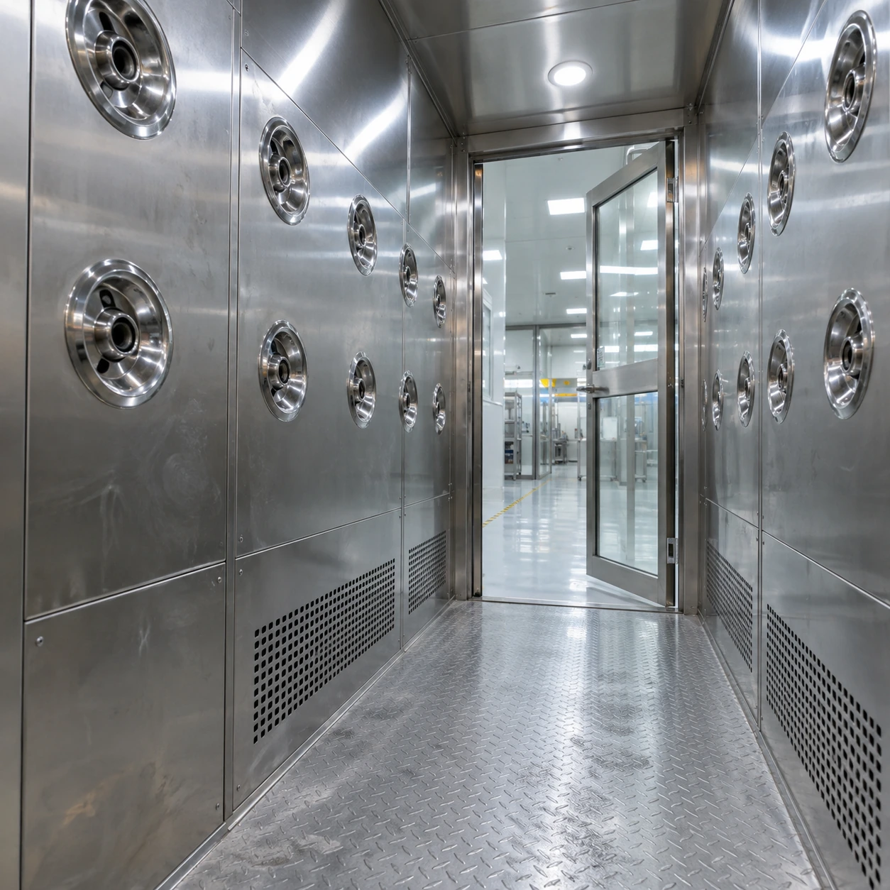
high velocity air shower
Product specifications
| Spec | Configuration |
|---|---|
| Jet system type | Air shower with directed high-velocity nozzle banks and a filtered particle-collection loop. |
| External reference sizes | Compact coverage: 1400 × 1000 × 2100 mm Deeper coverage: 1400 × 1500 × 2100 mm Extended coverage: 1400 × 2000 × 2100 mm W × D × H reference layouts; final dimensions follow the approved configuration drawing. |
| Internal working zone | Clear standing width and depth selected around garment exposure; door opening remains a separate access dimension. |
| Nozzle configuration | Adjustable side nozzles; one-sided, opposing-side or assessed upper coverage. |
| Velocity specification | Specified in m/s at an agreed nozzle measurement position and operating condition, according to the selected duty. |
| Blower duty | Fan selected against installed filter resistance; supported speed-control option where part of the chosen design. |
| Filter arrangement | Accessible prefilter and documented final particle filter with sealed installation. |
| Returns and interior | Low collection grilles kept clear of the wearer; cleanable stainless interior option. |
| Operating controls | Adjustable duration, door interlock and visible cycle state; filter-resistance indication option for maintenance. |
Jet direction, coverage and chamber size can suit the garments, particle-removal duty and available installation space.
Jet speed matters at the garment, together with direction, coverage and particle collection.
A fast nozzle is only part of the result.
A high velocity air shower uses concentrated jets to disturb loose particles on exposed surfaces. A nozzle reading describes air speed at a measurement location. It does not describe the speed at every garment surface, or prove a particular surface-removal percentage.
Distance and aim change how the jet reaches the wearer. A nozzle directed past the body can show a strong reading while doing little useful work. A coat fold, an object carried in front or another person can shield the surface even with ample fan power.
Direction and coverage
Adjustable nozzles can be aimed toward the intended garment zones. One-sided, opposing-side and additional top blowing are configuration choices with different coverage and occupied-space demands.
Fan and filter resistance
Specify the fan duty with the selected prefilter and final filter installed. More restrictive filtration or blocked returns can reduce jet delivery; extending the timer does not restore air speed.
Comfort and stability
Excessive noise, uncomfortable jets or loose items being displaced can cause poor use. Choose an operating condition that exposes the required surfaces while keeping the wearer stable and able to follow instructions.
Make the performance requirement measurable.
State nozzle velocity in m/s with the measurement position, instrument method and operating condition. Distinguish this from average chamber air speed and the room's ventilation rate. Agree which nozzles are checked and how readings are compared after maintenance.
Useful options include adjustable cycle time, documented final filter grade, accessible prefilters and differential-pressure indication. A speed-controlled blower, where selected and supported by the design, can help adjustment; it still requires a defined operating setting and limits.
When readings fall, check filter resistance, return obstruction, nozzle condition and blower operation. After the cause is corrected, confirm the same measurement condition rather than comparing figures taken at different distances.
These W × D × H configuration planning examples do not define velocity, removal efficiency or user capacity. Final dimensions follow the approved drawing, with internal clear width and door opening stated separately. Match the nozzle arrangement to those internal dimensions rather than to the enclosure label.
Custom configurations are available to suit the installation space, jet coverage, traffic and particle-removal application.