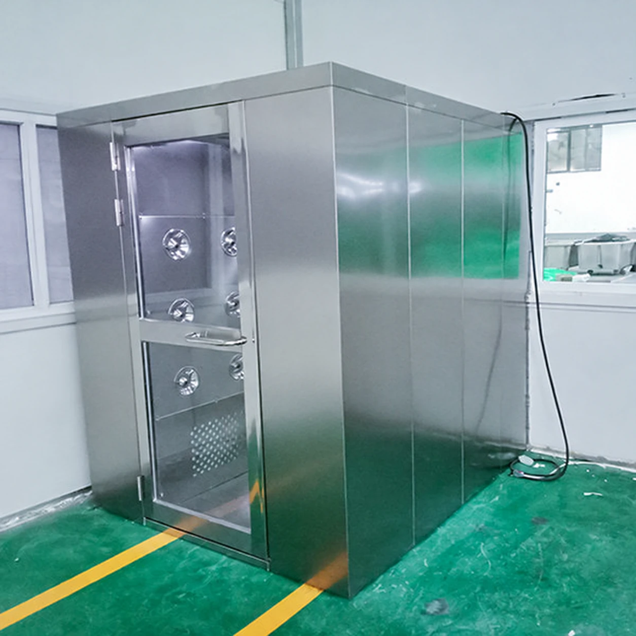
cleanroom air shower
Product specifications
| Spec | Configuration |
|---|---|
| Equipment format | Cleanroom personnel air shower configured for routine entry and maintainable operation. |
| External size range | Short chamber: 1400 × 1000 × 2100 mm Intermediate depth: 1400 × 1500 × 2100 mm Extended depth: 1400 × 2000 × 2100 mm Reference W × D × H; final dimensions follow the approved configuration drawing. |
| Clear standing space | Reference internal W × D × H: 800 × 910 × 1980, 800 × 1410 × 1980 or 800 × 1910 × 1980 mm. |
| Construction options | Full stainless enclosure or stainless interior with coated external cabinets. |
| Garment coverage | One-sided or opposing-side jets positioned for the garment and intended standing locations. |
| Filter maintenance | Accessible replaceable prefilter and documented final filter; filter-resistance indication can support maintenance trending. |
| Timer management | Adjustable duration with supervisor access; cycle-counting option for recording use. |
| Door status | Visible occupied and door-state indications; defined reset and sensor-fault behaviour. |
| Cleaning access | Removable lower grille covers and service sections located outside the occupied standing zone. |
Configuration can follow your peak arrivals, garment routine, maintenance access and installation space.
Select an entrance that stays usable as garments, traffic and maintenance needs change.
Design for the working day.
Cleanroom air shower selection begins with the particles carried on the outside of the garments and the way people enter the room. An occasional inspection team, a shift change and a steady stream of operators create very different entry demand. A chamber should be chosen for the busiest realistic period, while preserving the standing space needed to expose garment surfaces to the jets.
People standing closely together shield each other from the airflow. Increasing the permitted group size without reviewing jet positions can shorten a queue while weakening coverage. A larger envelope is useful only when the operating positions and the return path are designed with it.
Before installation
Measure the doorway and the route from unloading point to installation area. Check voltage, phase, frequency and electrical isolation. Locate service panels where technicians can open them without entering a production workstation or removing wall furniture.
Agree an entry sequence that fits the site's gowning routine. Adjustable time is useful, but staff need one clear approved setting and a visible indication of cycle progress.
During operation
Keep grilles clear and remove discarded wipes or overshoes from the chamber. Garment changes can affect comfort and coverage; long coats, hoods and bulky sleeves deserve review in the actual standing positions.
Watch for practical causes of bypassing: unclear indicators, unexpected door delays and queues outside the changing room. Correct the workflow instead of relying only on instructions to be patient.
At maintenance
Record a starting condition for jet operation and filter resistance according to the equipment procedure. A weaker jet can result from restricted filters, obstructed grilles or a fan fault; changing the timer does not restore the missing airflow.
Maintain doors, seals and sensors as part of the same entry system. A sound filter cannot compensate for a door that repeatedly fails to close.
Plan capacity without losing clear space.
External W × D × H configuration planning examples, in mm: 1400 × 1000 × 2100 for a compact entry, 1400 × 2000 × 2100 for a deeper arrangement, and 2300 × 3000 × 2200 for a wider group chamber requiring a reviewed user-position layout. These examples do not establish a rated persons-per-cycle figure. Show internal clear width, door clear opening and service envelope independently.
For a project brief, identify the peak arrival pattern, garment type, likely future headcount and whether exit traffic uses another route. Then compare arrangements by the full door-to-door cycle, maintenance access and standing coverage.
Choose service features before they are needed.
Accessible replaceable prefilters simplify routine attention to coarse dust loading. A filter-resistance indicator is an option for trending the selected filter stage, while labelled blower sections help identify a fault in a longer installation. Removable lower grille covers make settled debris easier to reach during cleaning.
Timer access can be restricted to supervisors so the established shower duration remains consistent. A cycle counter can help record use; an automatic reset for an empty entry event can reduce unnecessary lockouts when supported by the chosen controls. Select visible door-state indicators and documented sensor-fault behaviour to help staff distinguish an occupied cycle from a fault.
Custom configurations are available for the installation space, traffic profile, garment routine and application.