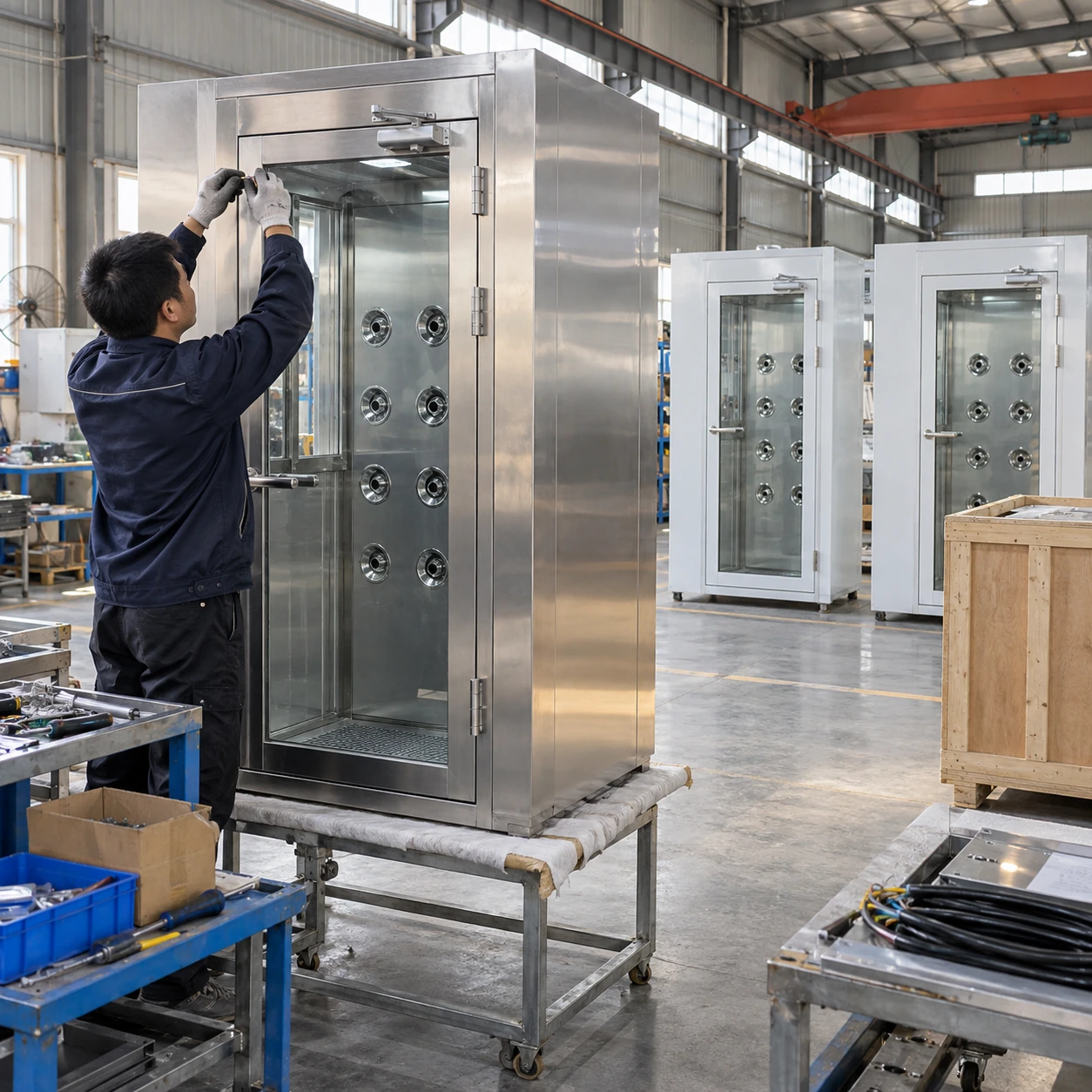
clean room air shower manufacturers
Product specifications
| Spec | Configuration |
|---|---|
| Selectable cabinet architecture | Single-sided, opposing-jet or long chamber; working entry route defines the configuration. |
| Outside W × D × H | Single-sided reference: 1200 × 1000 × 2100 mm. Opposing reference: 1400 × 1000 × 2100 mm. Long reference: 1400 × 2000 × 2100 mm. |
| Inside clear W × D × H | Compact references: 800 × 910 × 1980 mm. Long reference: 800 × 1910 × 1980 mm; clear doorway specified independently. |
| Enclosure specification | Full stainless, stainless-lined coated enclosure or panel construction, with selected finish and joint details. |
| Air-distribution choices | Single-sided, opposing side banks or additional overhead outlets where designed around the exposure positions. |
| Filtration specification | Documented final-filter option, prefilter, seal method and withdrawal route matched to the blower duty. |
| Door specification | Manual hinged or powered alternatives; frame, glazing, sensing and release behaviour selected as one assembly. |
| Controls and destination supply | Defined sequence, optional condition indication and site-matched voltage, phase and frequency. |
| Configuration evidence | Drawings, component references and agreed functional checks describe the supplied equipment and installation interfaces. |
Reference dimensions for layout planning. Final dimensions and selected construction follow the approved configuration drawing.
Materials, doors and air distribution can be selected together for the required entry route, usable space and maintenance duty.
A cleanroom air shower specification should make different construction options comparable. Define the working entrance first, then assess how the enclosure, filtration and controls deliver that arrangement.
The product specification is a set of connected choices
A manufacturer can change cabinet material, door format and air distribution to suit the site. Those choices are not interchangeable upgrades. A wider cabinet may house opposing jets without providing a wider passage. A powered door may resolve a swing conflict while requiring additional cleaning and sensor maintenance. A higher filter designation does not compensate for an unsuitable garment-exposure pattern.
The useful specification describes the desired result: a controlled personnel route, sufficient usable space, accessible maintenance and a defined cycle. It then states the construction and component requirements needed to support that result. This gives the project a clear basis for configuration and acceptance.
Turn broad descriptions into selectable options
| Requirement | Configuration choices | What the choice resolves |
|---|---|---|
| Cleanable enclosure | Full stainless; stainless interior with coated exterior; panel-built cabinet | Cleaning exposure, surface durability and connection details |
| Garment exposure | Single-sided, opposing side jets, additional overhead distribution where designed | Coverage around the intended standing positions and movement |
| Door operation | Manual hinged doors; powered alternatives with appropriate sensing | Available approach space, handling needs and the operating sequence |
| Filtration and service | Prefilter access, final-filter sealing, condition indication and a defined removal route | Routine upkeep without disrupting the room interface unnecessarily |
Review the same dimensional basis
Use mm throughout the layout. The reference examples below separate outside cabinet dimensions from inside clear space. Final dimensions follow the approved configuration drawing.
1200 × 1000 × 2100 outside
Inside clear W × D × H: 800 × 910 × 1980. A compact single-sided arrangement; the user movement must expose the garment to the supplied side.
1400 × 1000 × 2100 outside
Inside clear: 800 × 910 × 1980. The larger outside width accommodates opposing jets, not extra interior width.
1400 × 2000 × 2100 outside
Inside clear: 800 × 1910 × 1980. More longitudinal space requires a matched nozzle pattern and defined occupancy.
Clear door width, door height, swing, filter access and the surrounding wall opening are additional dimensions. Agreeing those details prevents apparently equivalent cabinet sizes from producing different installed routes.
Agree what will demonstrate the supplied configuration
Drawings demonstrate geometry. Component records identify what is fitted. Functional checks demonstrate the programmed sequence. Airflow and filter-related checks describe particular equipment conditions. None alone proves that the entire facility will achieve its required cleanliness.
Set an acceptance method that relates to the planned use, including door operation, service access and the final room connection. Record measurement conditions so later maintenance readings have a useful baseline. For the project team, that produces a cabinet that can be installed, operated and kept in service with fewer unresolved details.
Custom configurations are available to suit the installation space, traffic and application, with the specification developed around the intended entry route.