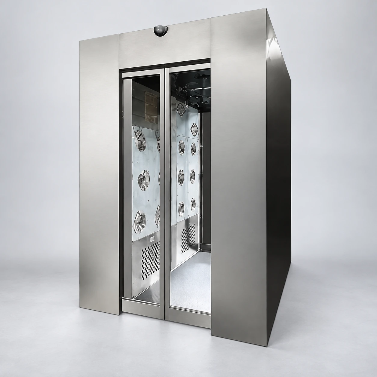
air shower manufacturer
Product specifications
| Spec | Configuration |
|---|---|
| Manufacturing configuration | One-sided, opposing-jet or extended cabinet, with wall attachment and service-panel positions defined together. |
| Outside W × D × H | One-sided reference: 1200 × 1000 × 2100 mm. Opposing-jet reference: 1400 × 1000 × 2100 mm. Extended reference: 1400 × 1500 × 2100 mm. |
| Inside clear W × D × H | Both compact references: 800 × 910 × 1980 mm. Extended: 800 × 1410 × 1980 mm. |
| Panel construction | Full stainless or stainless-lined coated enclosure; finish, joints and reinforcement selected for the cleaning and contact duty. |
| Filter assembly | Documented final-filter option with a matched frame, gasket, clamping method and removal direction. |
| Plenum and outlets | Nozzle positions and supply distribution designed for the selected chamber length, rather than extended panels alone. |
| Door assembly | Glazing, seals, hinges and closer arrangement coordinated with the interlock and required handling. |
| Controls and supply | Programmable cycle and closure sensing; electrical components selected for the destination voltage, phase and frequency. |
| Handover information | Configuration drawing, wiring information, settings and replaceable component references matched to the supplied assembly. |
Reference dimensions for layout planning. Final dimensions and construction details follow the approved configuration drawing.
Materials, door assemblies, filter access and cabinet interfaces can be configured around the installation space and intended entry duty.
The manufacturing brief connects the enclosure, air circuit and doors. When those parts are designed separately, a cabinet can fit the drawing yet remain awkward to clean, operate or service.
Start with the interfaces that cannot be changed easily
An air shower manufacturer needs more than a nominal width and a nozzle count. The finished cabinet must meet the wall opening, floor level, door approach, power connection and maintenance route. An incorrectly positioned service panel can be hidden behind the cleanroom wall after installation; correcting it later can require dismantling equipment that is otherwise working.
The dimensional drawing should therefore show the outside envelope, internal standing space, clear door opening, wall attachment and removable panels. Filter access is a physical requirement, not a note to add after the cabinet has been fabricated. Door handing and the control-panel side should be fixed while the layout can still be changed.
What the manufacturing specification needs to resolve
Panels, joints and edges
Specify the interior and exterior materials separately. A stainless interior with a coated exterior is a different construction from a fully stainless cabinet. Joints, glazing retainers and fasteners need accessible cleaning surfaces. The finish around welds and cut edges affects both appearance and routine care.
Filter seat and supply plenum
A filter rating does not describe the entire cabinet. The filter must seat correctly, the seals must be serviceable and the plenum must feed the intended outlets. Fan selection must account for the filters and circuit resistance, including the expected change as the filters load.
Fit through repeated operation
Door leaves, hinges, closers and latches form a working assembly. Specify how the doors interact during entry, departure, a failed cycle and emergency release. A stiff closer may improve closure but make the door difficult for some users; that trade-off belongs in the design review.
Size references for the fabrication discussion
The following cabinet families are reference examples for space planning. All measurements are mm. They illustrate the difference between outside dimensions and usable internal dimensions; final dimensions follow the approved configuration drawing.
| Construction arrangement | Outside W × D × H | Inside clear W × D × H | Design decision |
|---|---|---|---|
| One-sided jet cabinet | 1200 × 1000 × 2100 | 800 × 910 × 1980 | Reduced equipment width with a defined user turning procedure |
| Opposing jet cabinet | 1400 × 1000 × 2100 | 800 × 910 × 1980 | Two-sided exposure while retaining the same reference standing space |
| Extended opposing jet cabinet | 1400 × 1500 × 2100 | 800 × 1410 × 1980 | Longer interior with a revised outlet distribution |
Increasing the enclosure depth should prompt a review of outlet positions and return paths. It should not simply stretch a short cabinet while leaving the air distribution unchanged.
A useful handover follows the built equipment
The final drawings, wiring information, control settings and replaceable component references should match the cabinet supplied. This makes it easier to diagnose a door fault or order a filter without guessing from a similar product photograph. Define factory checks and site checks separately: installation can alter door alignment, seals and the interfaces with room ventilation.
Discuss the acceptance method before fabrication, including how airflow readings are taken, what door states are tested and how filter installation is checked. A photograph of a finished enclosure cannot answer those questions.
Custom configurations are available to suit the installation space, traffic and application, including enclosure materials, access panels and door arrangements.