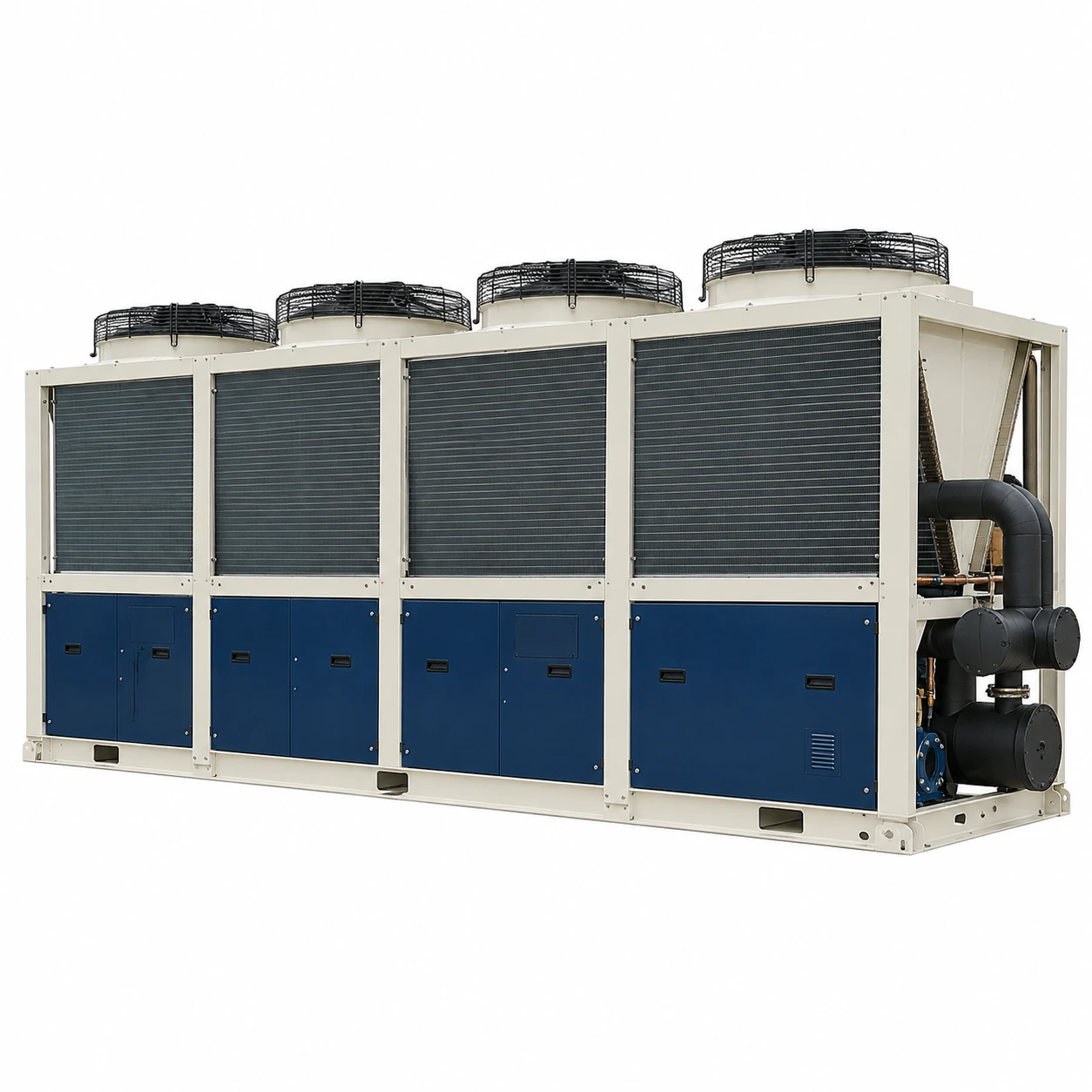
Air-Cooled Chillers
60 ton air cooled chiller
| Brand | shengtongJH |
|---|---|
| Nominal cooling duty | 60 US RT = 211.01 kW thermal |
| Capacity arrangements | Staged scroll package or screw compressor configuration |
| Calculated flow at 5 K water rise | 36.29 m³/h |
| Temperature selection | Common chilled-water supply duties of 7–15°C; selection at the required return and ambient conditions |
| Envelope options, L × W × H (mm) | Approximately 3,500–5,000 × 1,800–2,300 × 2,000–2,500 |
| Pump options | External duty pump; duty/standby or secondary distribution options |
| Power supply | Three-phase industrial supply, matched to destination voltage/frequency |
| Control functions | Temperature staging, flow proving, remote alarm and restart management |
| Environmental options | Coil protection and winter operation package where required |
This is a configurable capacity class. Confirm the selected unit's performance, minimum flow, electrical input and dimensions before installation.
Capacity control, pumps, buffer storage and environmental protection can be customized to the site's production pattern.
A 60 ton air cooled chiller is useful where a production zone has outgrown individual small cooling units but does not need a very large central plant. Variable production makes its minimum cooling step and water-side control particularly important.
Reduced production can be the difficult condition
At full output the chiller may run steadily, yet during lunch breaks or overnight it may cycle repeatedly. The important comparison is between the smallest stable refrigeration step and the heat still entering the loop. A large label capacity does not describe how smoothly the unit can follow a small load.
Adding useful water volume can slow temperature changes, while finer compressor control can reduce the mismatch. These measures address different causes. Buffer sizing should follow the selected equipment and operating pattern, rather than a universal litres-per-ton rule.
Keep flow when branches close
Production valves can reduce circulation as tools stop. The evaporator still has a minimum flow requirement. A properly controlled bypass, separate primary circulation or an approved variable-flow strategy can preserve that requirement. The correct arrangement depends on the selected chiller and distribution system.
Make restarting predictable
After a shift change or power interruption, several loads may demand cooling together. Coordinate pump operation and compressor restart so the system proves circulation before refrigeration returns. Avoid treating every temperature deviation as permission for an immediate compressor restart.
Practical access lowers disruption
A serviceable unit allows the coil to be cleaned, the strainer basket removed and the pump or compressor reached without dismantling the production network. Include isolation and drainage where those tasks require them. For an outdoor installation, assess whether winter protection must remain powered when production is shut down.
Use trend data to distinguish capacity problems from distribution problems: supply and return temperature, active compressor stage and process flow tell a more useful story together than the temperature display alone.
If the installation will later serve multiple buildings, review the complete chiller system rather than extending hoses from a local package.
Capacity control, pumps, buffer storage and environmental protection can be customized to the site's production pattern.