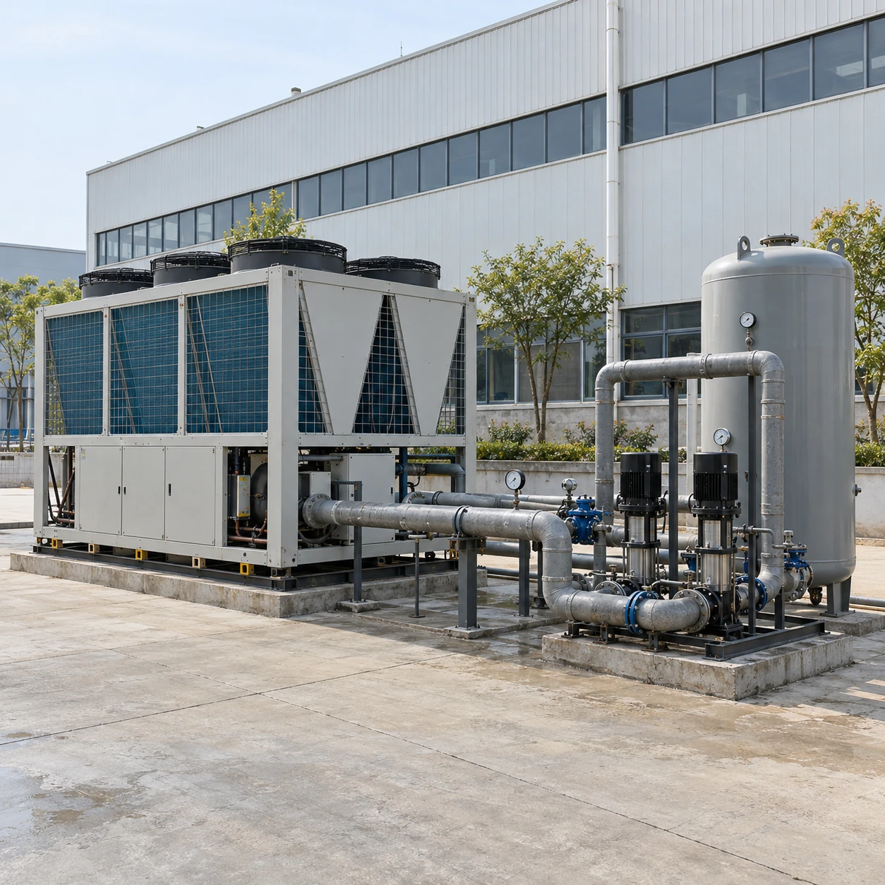
Air-Cooled Chillers
air cooled chiller system
| Brand | shengtongJH |
|---|---|
| System formats | Single packaged unit; modular parallel plant; separate chiller and hydraulic skid |
| Nominal plant sizes | 20 / 60 / 100 / 200 RT and project-sized combinations |
| Hydraulic layouts | Constant primary flow; primary-secondary; variable primary where the selected evaporator permits it |
| Temperature basis | Supply and return temperatures defined by the process; 7/12°C is one common selection condition |
| Buffer and expansion | Buffer volume calculated from minimum active capacity and cycle time; expansion arrangement matched to open or closed loop |
| Pump selection | Duty/standby options; flow and head selected from the complete circuit |
| Module size options, L × W × H (mm) | Packaged modules around 2,500 × 1,700 × 2,000 or 4,000 × 2,000 × 2,200; tank and pump skid additional |
| Power and control | Three-phase supply; staged unit sequencing, remote enable and alarm interface options |
| Process separation | Plate heat exchanger and secondary circuit where fluid quality or pressure requires separation |
System dimensions include the selected equipment only when explicitly listed; pipework, service aisles and airflow clearances must be added to the installation layout.
Plant capacity, pump duty, buffer volume and sequencing can be customized around your production loads and expansion plan.
A complete air cooled chiller system connects refrigeration capacity to the machines that need it. The chiller, pumps, pipework, buffer volume, water treatment and controls must work together as production starts, stops and changes load.
Why a correctly sized chiller can still give unstable cooling
A production valve closes, flow falls and the evaporator loses the water movement it needs. Alternatively, a small loop heats and cools so quickly that the compressor repeatedly starts and stops. These are hydraulic and control problems; adding another refrigeration unit may leave them unchanged.
Start with a schedule of connected loads, identifying which operate together, their permitted temperature range and whether their control valves vary flow. The lowest overnight load matters as much as the highest daytime load because it determines how gently the plant must unload.
Separate circulation duties when they are different
A primary-secondary arrangement can maintain suitable evaporator circulation while a separate pump follows the production network. It adds equipment and can introduce mixing, so it is not automatically the best solution. Variable-primary operation can reduce pumping equipment but requires compatible evaporators, flow limits and a control sequence that manages changes safely.
A buffer vessel provides thermal mass. An expansion vessel accommodates fluid expansion in a closed circuit. Neither automatically performs the other function, and a tank only contributes useful buffering if the water actually circulates through it.
A useful start and stop sequence
Establish water movement
Open the required path, start the selected pump and prove adequate flow before enabling refrigeration. A pump-running signal alone does not prove flow.
Match the active load
Stage compressors or complete units according to temperature and operating limits. Rotate duty where appropriate without overriding minimum run and restart times.
Manage an interruption
Define the response to lost flow, pump failure and a unit alarm. Maintain post-run circulation where required and prevent uncontrolled simultaneous restarts.
Build expansion into the interfaces
Future capacity needs more than an empty pad. Reserve electrical capacity, header connections, isolation valves, control addresses and a route for delivery. A larger future pump may exceed existing valve or heat-exchanger pressure limits, so review the network rather than merely increasing the motor size.
Commissioning should confirm branch flows, sensor positions, supply/return temperatures and the sequence under both full and reduced production. This makes the system's behaviour understandable to the operators who will use it every day.
Plant capacity, pump duty, buffer volume and sequencing can be customized around your production loads and expansion plan.