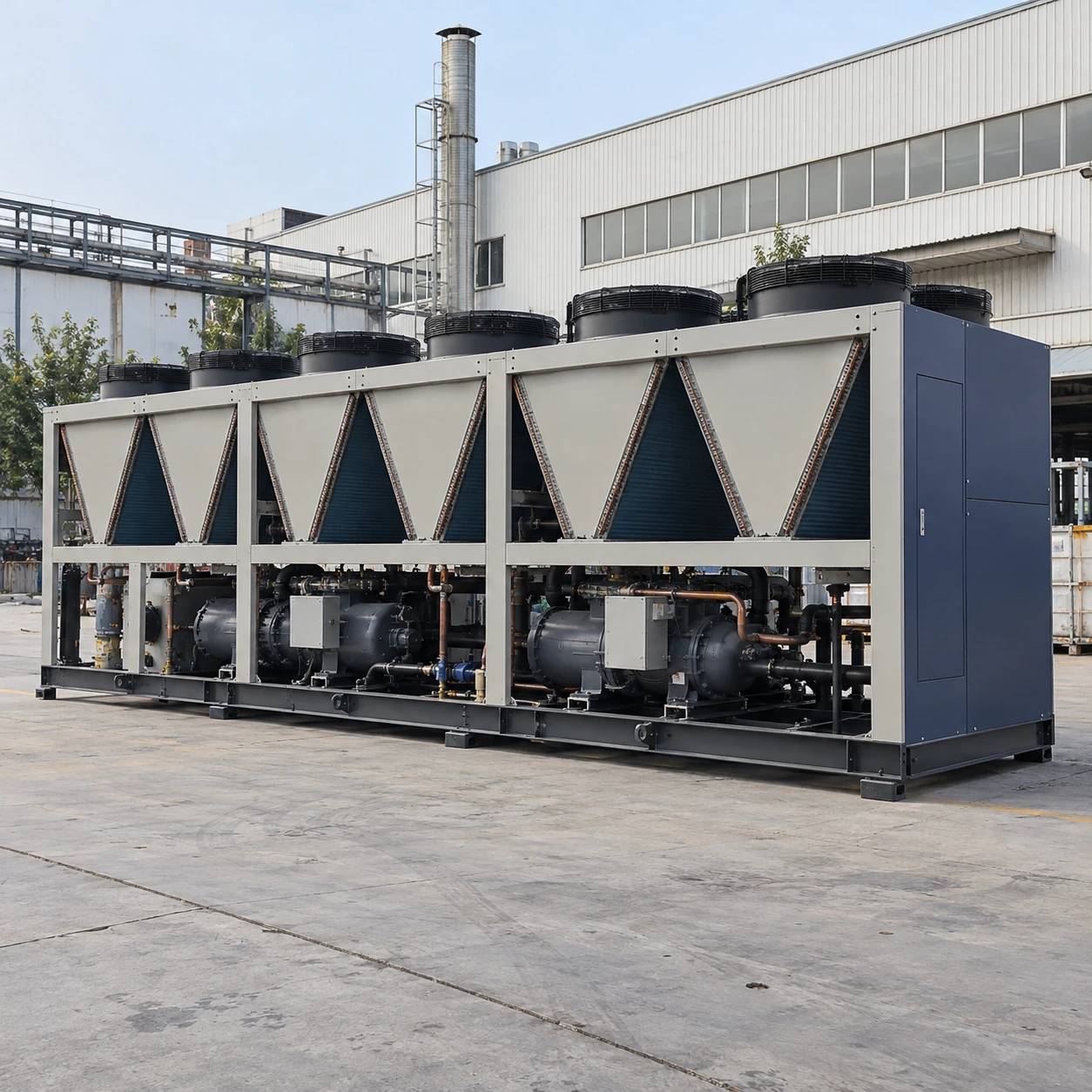
Air-Cooled Chillers
200 ton air cooled chiller
| Brand | shengtongJH |
|---|---|
| Nominal duty | 200 US RT = 703.37 kW thermal |
| Equipment arrangements | Single large screw unit or coordinated smaller units with the same required duty |
| Calculated water flow at 5 K rise | 120.98 m³/h, water only |
| Temperature selection | Positive-temperature chilled-water duty; site-specific summer and part-load selection |
| Hydraulics | Separate pump station, isolation, strainer, expansion and buffer equipment as required |
| Single-unit envelope options, L × W × H (mm) | Approximately 8,000–12,500 × 2,000–2,600 × 2,100–2,800 |
| Supply | Three-phase industrial supply; feeder sizing from the selected unit's electrical data |
| Capacity control | Screw unloading or staged compressor/circuit operation, depending on package |
| Plant interfaces | Remote enable, common alarm, water-temperature signal and communication options |
A single-unit envelope does not describe a multi-unit installation. Confirm cooling performance and service clearances for the chosen arrangement.
Unit quantity, redundancy, water-side equipment and control integration can be customized for your plant's operating schedule.
A 200 ton air cooled chiller is a central-plant choice for sustained industrial loads. At this scale, the decision includes how much cooling remains during maintenance, how water is distributed and how the plant operates when production falls.
Central capacity
Decide what must keep running
If all cooling disappears when one machine is serviced, nominal capacity alone does not meet a continuous-production requirement. Identify essential process loads separately from loads that can stop or reduce output. The available cooling after an outage should be compared with that essential demand.
Two units that together reach the required total provide staging flexibility, but they do not automatically provide full standby capacity. If one stops, the remaining unit must either carry the essential load or the control system must shed nonessential consumers.
Choose a hydraulic arrangement that supports staging
Parallel evaporators need balanced flow and appropriate isolation. Water flowing through an inactive unit can mix with the active supply, while an incorrectly closed path can deprive a running unit of flow. Unit sequencing and pump/valve sequencing therefore need to be designed together.
Variable production demand can change the system pressure significantly. Select the pump control from the distribution network's requirements, and keep the evaporators within their allowable flow range. A differential-pressure target at the wrong point can leave remote process branches short of water.
Make the utility yard maintainable
Provide access for coil cleaning, compressor service and heat-exchanger work, as well as the original crane delivery. A later building extension or screen wall must not block condenser air intake. Assess noise at the site boundary using the selected operating condition rather than a generic sound number.
Define the handover evidence
Record the selected duty, ambient basis, minimum unloading level, fluid concentration and electrical demand. During commissioning, check flow proving and unit changeover at reduced load. These records make later expansion and fault diagnosis much more straightforward.
For larger resilient plants, see the 500 ton configuration discussion.
Unit quantity, redundancy, water-side equipment and control integration can be customized for your plant's operating schedule.