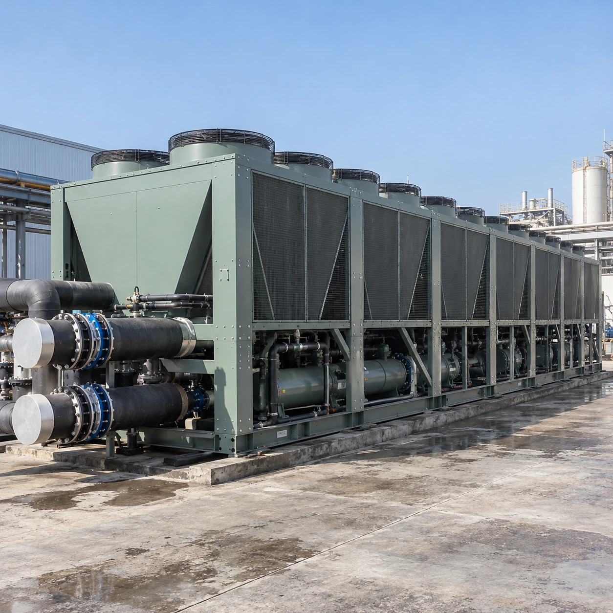
Air-Cooled Chillers
500 ton air cooled chiller
| Brand | shengtongJH |
|---|---|
| Nominal duty | 500 US RT = 1,758.43 kW thermal |
| Plant formats | Large screw chiller; coordinated smaller-unit bank |
| Calculated flow, water / 5 K rise | 302.45 m³/h total duty flow |
| Heat rejection | Outdoor air-cooled condenser banks; open discharge path required |
| Single-machine envelope class, L × W × H (mm) | Approximately 15,100 × 2,250 × 2,520; actual design and transport sections vary |
| Hydraulics | Engineered pump/header assembly with isolation, flow verification and expansion provision |
| Electrical data | Industrial three-phase supply; single or multiple feeds according to selected equipment |
| Sequencing | Lead/lag, capacity staging, load shedding and standby strategies by project |
| Delivery information | Certified lifting points, shipping sections and operating loads supplied for the selected equipment |
The envelope is a size class, not an approved installation drawing. A bank of smaller units needs its own layout, air spacing and access calculation.
The unit bank, standby strategy, electrical interfaces and water-side plant can be customized around your critical production demand.
A 500 ton air cooled chiller project is a plant-infrastructure decision. Large single machines and coordinated unit banks can meet this duty, but they differ in outage exposure, staging, lifting requirements and the amount of equipment that must remain available during service.
Define the capacity that must survive a failure
Two units each supplying half the total duty can provide all required cooling together. They cannot maintain that total with one unit out of service. Where full duty must survive one outage, the installed arrangement needs additional available capacity, assessed at the same actual operating conditions.
For instance, a three-unit plant with two units required for duty and one available as standby can provide unit-level redundancy. That arrangement still depends on the pumps, power supplies, headers and controls. A common component can remain a single point of failure even when spare refrigeration capacity exists.
Part-load behaviour shapes the whole year
A large factory may have a high summer peak but a much smaller night or seasonal load. Compare the controllable range of a large machine with the staging steps of a unit bank. The decision affects compressor cycling, pump operation, maintenance flexibility and how efficiently the plant follows production.
Cooling-water temperature should be no lower than the process requires. Resetting it upward during suitable operating periods may reduce refrigeration lift, but only if every connected process and control valve can tolerate the change.
Electrical infrastructure
Cooling output is not the incoming electrical demand. Use selected-unit input, starting characteristics and feeder requirements to assess transformers, distribution and restart sequencing.
Delivery and structure
Check transport dimensions, crane reach, lifting mass and foundation reactions. Operating mass includes fluid and accessories; shipping mass alone is not a structural design basis.
Heat rejection
A machine rejects the process heat plus compressor energy. Yard layout must accommodate that warm air without trapping it between walls or neighbouring equipment.
Specify acceptance around operating scenarios
Agree the duty point, selected fluid and concentration, control communications and permitted operating envelope before purchase. Include planned changeover, loss of one unit, loss of a duty pump and recovery after power interruption in the commissioning sequence. Factory test evidence and site commissioning serve different purposes; one should not be presented as a substitute for the other.
The unit bank, standby strategy, electrical interfaces and water-side plant can be customized around your critical production demand.