Air-Cooled Chillers
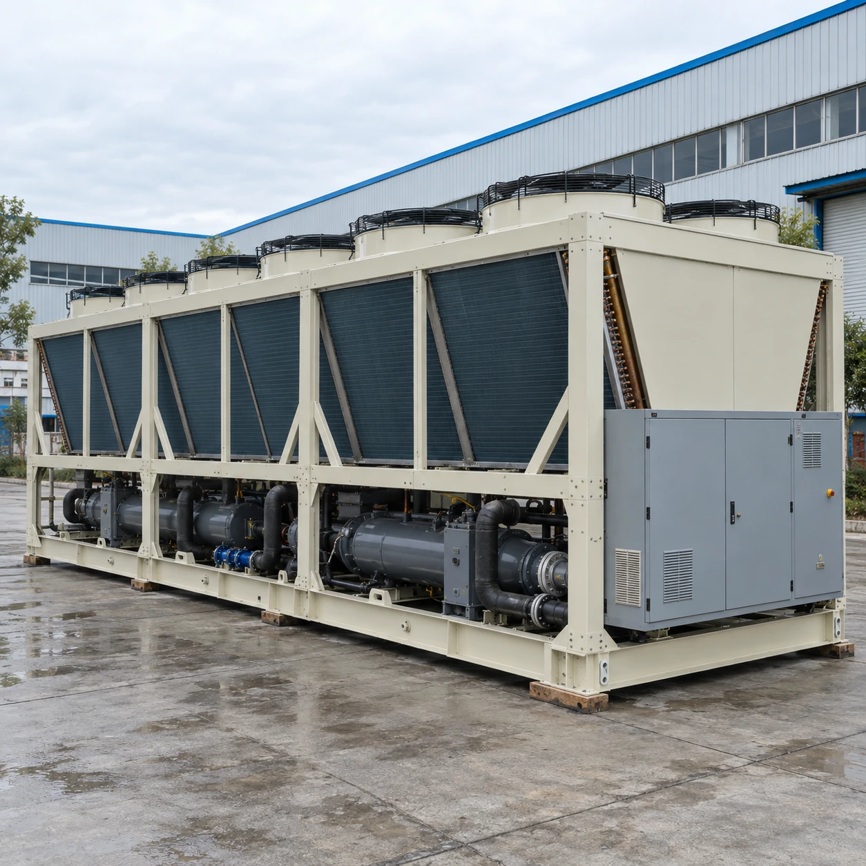
150 ton air cooled chiller
| Brand | shengtongJH |
|---|---|
| Nominal duty | 150 US RT = 527.53 kW thermal |
| Compressor arrangement | Screw or multi-compressor package |
| Calculated water flow at 5 K rise | 90.74 m³/h |
| Water connection arrangement | Flanged connections and isolatable branches, sized for the selected evaporator |
| Envelope options, L × W × H (mm) | Approximately 6,000–9,000 × 2,000–2,600 × 2,100–2,800 |
| Pump package | Separate pump selection; existing-system interface or new hydraulic module |
| Power | Three-phase industrial supply; operating input and starting requirements supplied with selection |
| Control integration | Existing plant enable, staging, alarm and communication interfaces by agreement |
| Outdoor options | Coil treatment, vibration isolation and winter protection as required |
Existing pipework and power infrastructure must be checked against the selected machine. Nominal capacity alone does not establish retrofit compatibility.
Water connections, controls, plant staging and installation arrangements can be customized for your factory expansion.
A 150 ton air cooled chiller is often considered when a factory extends an existing cooling network. The new unit must match the network's temperatures and pressure limits while addressing the additional production load.
Check what the old system was designed to carry
A larger cooling machine can expose restrictions in headers, pumps and branch valves. If the existing pipes cannot carry the required flow without excessive pressure loss, additional refrigeration will not deliver its benefit to the new production area.
Measure the present supply and return temperatures under load and check whether the original design temperature difference is actually achieved. Low return temperature from unnecessary bypassing can consume available flow without carrying useful heat, making the plant seem smaller than it is.
Hydraulic interface
Confirm allowable pressures, branch balance, evaporator flow limits and the need for primary-secondary separation. Review whether existing pumps remain within their useful operating range.
Electrical interface
Assess available feeder capacity and starting behaviour. A cooling-duty number cannot be used as the electrical input rating.
Control interface
Define which controller requests capacity, starts pumps and handles alarms. Avoid two independent controllers repeatedly enabling and disabling one another.
Install without contaminating the operating loop
New pipework can introduce debris, welding residue and air. Plan flushing, cleaning and water treatment before connecting it to the active evaporators. Temporary strainers and isolation arrangements should be included where the commissioning plan requires them.
Schedule cutovers around the process's acceptable interruption. Temporary cooling or staged branch connection may be appropriate where a single shutdown would stop critical production.
Verify both the new duty and the old loads
After expansion, check flow and temperature at the existing branches as well as the new ones. A newly opened low-resistance branch can change the balance of the whole network. Compare stable full-production operation with reduced load, and record the final valve settings and control sequence.
Where continued operation during maintenance is important, compare the new machine with an equivalent parallel plant arrangement before committing to the final footprint.
Water connections, controls, plant staging and installation arrangements can be customized for your factory expansion.