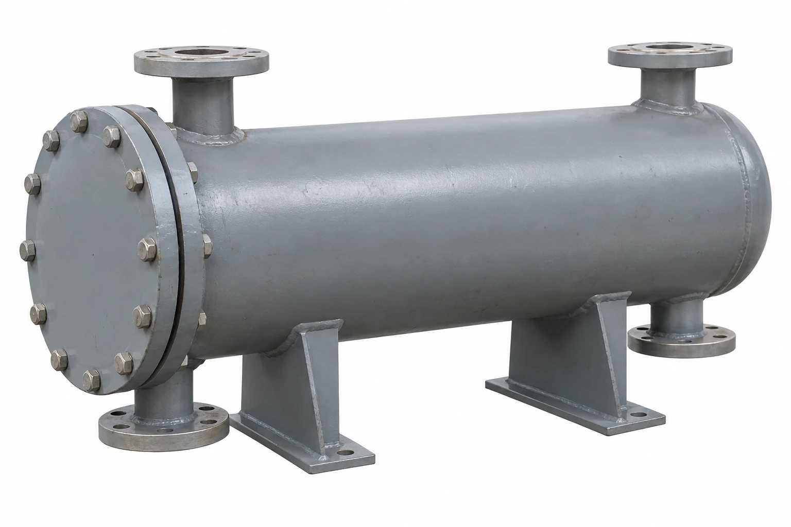
Plate Heat Exchangers
shell and plate heat exchanger
| Brand | shengtongJH |
|---|---|
| Core construction | Welded plate pack within a cylindrical shell |
| Plate material choices | 304L / 316L stainless steel; alternative alloy by review |
| Shell choices | Carbon steel or suitable stainless steel |
| Area enquiries | 1 / 5 / 10 / 20 m², subject to thermal selection |
| Connection choices | DN25 / DN50 / DN80; shell-side nozzles selected separately |
| Pressure enquiries | 10 / 16 / 25 bar at specified design temperatures |
| Mounting | Horizontal saddle supports or selected vertical arrangement |
| Dimensions | Shell diameter × overall length in mm; nozzle projection and removal space specified separately |
| Access options | Fixed or openable shell construction, depending on selected design |
| Service scope | Liquid-to-liquid duty; phase-change service requires a separate selection |
The shell and welded core are a matched pressure assembly. No universal temperature, pressure or interchangeable shell dimension is implied by these options.
Shell material, plate pack, nozzle positions and support arrangement can be customized to the process specification.
A shell and plate heat exchanger places a welded plate pack inside a pressure shell. It combines a compact plate-based heat-transfer core with a shell arrangement, and should be selected for a defined process rather than treated as a generic replacement for every framed exchanger.
Understand the two flow paths
One fluid passes through the plate-side channels and the other through the shell-side path around the corresponding plate surfaces. Internal flow-directing components are important to the intended distribution. The shell is therefore part of the thermal arrangement, not merely a protective cover.
Connection positions and pass arrangement must follow the selected design. Reversing or relocating nozzles to suit existing pipes without checking the internal path can change how the exchanger operates.
Access depends on construction
An openable shell may allow removal of a welded pack, while a permanently closed construction offers different service access. Neither arrangement means individual welded plates can be removed like gasketed plates. Identify which surfaces can be inspected and how deposits would be cleaned.
Specify each side's conditions
Pressure, temperature and fluid compatibility must be stated for both circuits. Include startup and shutdown conditions. A design suitable for ordinary water service should not be assumed suitable for refrigerant, steam or aggressive chemicals.
Plan the supports and removal route
A short vessel can still impose significant support and piping loads. Include nozzle projections, lifting points and any pack-withdrawal space in the layout. Independent pipe supports help avoid transferring avoidable stress into the shell connections.
If the installation is inside an existing plant room, check the delivery route as well as the final operating position. The removable end or service side should remain accessible after insulation and pipework are installed.
Use the construction where it provides a reasoned benefit
For a routine compatible water circuit with frequent plate cleaning, an ordinary gasketed unit may be simpler to maintain. A shell-and-plate arrangement deserves consideration when its welded construction and operating envelope address a real process need.
shengtongJH can review a defined equipment enquiry and coordinate suitable supplier options. The final pressure design and required inspection documents belong to the selected assembly; this listing does not claim an in-house pressure-vessel manufacturing facility.
Shell material, plate pack, nozzle positions and support arrangement can be customized to the process specification.