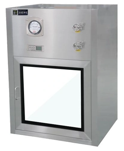
Pass Boxes & Material Transfer
Electronic Interlock Dynamic Pass Box
| Specification | JN-EIDPB-600 | JN-EIDPB-700 | JN-EIDPB-800 | JN-EIDPB-900 | JN-EIDPB-1000 |
|---|---|---|---|---|---|
| External dimensions (mm) | 800 × 680 × 1040 | 900 × 780 × 1140 | 1000 × 880 × 1240 | 1100 × 980 × 1340 | 1200 × 1080 × 1440 |
| Working chamber dimensions (mm) | 600 × 600 × 600 | 700 × 700 × 700 | 800 × 800 × 800 | 900 × 900 × 900 | 1000 × 1000 × 1000 |
| Airflow velocity setting | 0.45 m/s ±20% | ||||
| Air handling | Fan-driven filtered airflow | ||||
| Enclosure and doors | Brushed 304 stainless steel | ||||
| Door interlock | Electronic / magnetic | ||||
| Observation glazing | Double glazing; 5 mm tempered panes | ||||
| Electrical supply | 220 V / 50 Hz | ||||
| Controls | Adjustable clean-air cycle, countdown, door indication and alarm | ||||
| Size customization | Available | ||||
Dimensions and configurations can be customized for your application.
Add a filtered-air stage to material transfer between controlled rooms. The electronic interlock coordinates access while the fan and filter circulate air through the working chamber before the receiving door is released.
Give the chamber a controlled recovery step
Opening a transfer door introduces air and disturbance from the loading side. A dynamic pass box adds a fan-and-filter stage that removes airborne particles from the chamber air. The electronic interlock holds the receiving door until the selected transfer sequence permits release.
This differs from a static electronic interlock pass box, where the principal function is coordinated door access. A dynamic unit is appropriate when the process needs the chamber environment to recover between opening events, as well as a barrier against simultaneous door opening.
The load becomes part of the airflow arrangement
Leave a route around the material
A large tray can shield the space beneath it; a tall pack can obstruct the supply; a carton pushed against a return opening can restrict circulation. Select the working space around the loaded arrangement with clearance for air movement and handling. Packing in more items can increase transfer time if it prevents effective circulation.
Keep the chamber free of spare packaging and loose materials. The airflow is intended to manage airborne particles, not to strip stubborn deposits from irregular surfaces. Materials still need the preparation and cleaning procedure appropriate to the receiving room.
Set release using the intended transfer
The useful recovery period depends on the load, opening pattern and operating condition. Establish it during qualification with the intended loading arrangement, then keep that pattern consistent. A countdown communicates progress; it does not by itself verify particle concentration or microbial cleanliness.
Connect the air cycle to clear door states
The operating sequence should distinguish loading, both doors closed, clean-air operation and ready-to-unload. An incomplete door closure must not be mistaken for a completed transfer. Operators on either side need understandable indications so they do not pull against a locked door or leave the box open while waiting.
Define the response to power loss, fan failure and an interrupted cycle. A recovered controller must not silently release an unfinished load as though the cycle completed. Where an external room-control system needs signals, agree which system controls release and which only displays status.
Make filter care possible after installation
The upper equipment section needs service access in addition to the working chamber. Plan the replacement route for the filter, access to the fan and controller, and the location of test connections. A wall or ceiling installed too close to these components can make future maintenance unnecessarily disruptive.
Record airflow and filter-pressure readings at commissioning so later changes can be investigated against the installed condition. A pressure indication helps reveal changes in airflow resistance; it does not replace an integrity test. Following filter replacement or work that disturbs the filter seal, perform the checks required by the site's operating procedure before reuse.
Supply the transfer-load outline, wall arrangement and required receiving-room conditions. Chamber size, airflow configuration, service access and control sequence can be customized for your application. Discuss a dynamic transfer solution.