Operating Room Fixtures
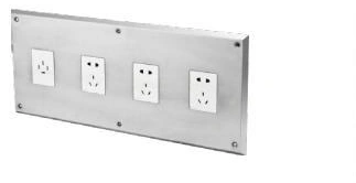
Operating Room Power Socket Panel
| Specification | Four positions | Five positions | Six positions |
|---|---|---|---|
| Brand | shengtongJH | ||
| Configuration enclosure, W × D × H (mm) | 523 × 100 × 220 | 643 × 100 × 220 | 763 × 100 × 220 |
| Face material | Stainless steel or coated metal | ||
| Socket interface | Project-selected UK / EU / US / regional socket type | ||
| Supply arrangement | Circuit voltage and protective system matched to the installation | ||
| Identification | Circuit labels and essential / normal supply marking | ||
| Mounting | Recessed or surface-mounted backbox | ||
| Options | Equipotential bonding terminals; separate data positions | ||
Dimensions and configurations can be customized for your application.
Bring the required power connections to one accessible wall location, with sockets and circuits arranged around the equipment used in the room.
Organize connections around the equipment plan
A row of sockets is useful only when the right circuit is available at the right position. Identify the connected equipment, plug types and supply requirements before selecting the panel. Normal and essential supplies should be clearly distinguishable according to the facility's electrical design.
Consider the plugs themselves. Large power supplies can obstruct adjacent outlets, and short leads may tempt users to add extension strips. Appropriate spacing and panel location can reduce this clutter and make the connection area easier to inspect and clean.
The panel is an interface, not an electrical protection system
The faceplate and sockets do not provide the complete protection arrangement required for a medical location. Circuit protection, earthing, any isolated power system and associated monitoring must be designed and installed by qualified personnel for the applicable requirements. A higher socket count does not increase the capacity of its upstream circuit.
Separate data and power interfaces as required by the installation design. Where equipotential bonding points are included, keep them identifiable and accessible. Avoid routing cables across walking paths, through door openings or over surfaces that need frequent cleaning.
Leave the backbox accessible
Installation
Allow enough recess depth for the socket bodies, wiring and cable bend space. Secure the box to suitable support and coordinate the perimeter with the wall finish. The face should be removable for planned electrical service.
Daily use
Keep labels readable and inspect damaged sockets or loose plugs promptly. The cleaning method must suit the fitted electrical components; an unverified enclosure should not be treated as washdown equipment. Socket count, regional interfaces and enclosure dimensions can be customized to the room's equipment schedule.