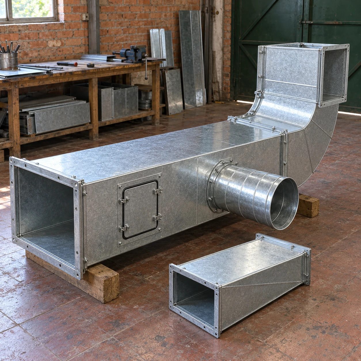
HVAC Ductwork
hvac ductwork
| Duct construction | Galvanized steel; spiral round or fabricated rectangular sections |
|---|---|
| Round connection diameters | Ø100 / 125 / 160 / 200 / 250 / 315 / 400 mm |
| Round straight-section length | 3,000 mm; shorter sections to suit the installation layout |
| Rectangular connection / length | 500 × 300 mm (W × H), with 1,500 mm straight-section length; custom cross-sections and lengths |
| Round wall-thickness options | 0.5 mm at Ø100–200; 0.6 mm at Ø250 / 315; 0.8 mm at Ø400 |
| Connections and fittings | Gasketed round couplings or rectangular flanges; bends, reducers, branches and access doors |
| Insulation options | External thermal insulation and vapour-control facing, selected for air temperature and surrounding conditions |
Sizes describe nominal duct connections, not the overall insulated envelope. Sheet thickness, reinforcement, joints and supports must be matched to the specified positive or negative pressure duty.
Duct shapes, section lengths, connection details, access openings and insulation arrangements can be customized to suit the HVAC layout and operating conditions.
HVAC ductwork carries supply, return and exhaust air between equipment and occupied or process spaces. Straight sections, bends, branches and transitions form one connected air route. Selecting them together helps avoid restricted airflow, mismatched joints and installation changes after fabrication.
Build the air route as a connected set
A duct package needs more than straight lengths. The outlet of an air handling unit, the route around structural beams and the final terminal connections all affect the fittings required. Resolve these interfaces before fixing the fabrication schedule.
Main runs
Carry the combined airflow along the distribution route. The cross-section and reinforcement need to suit the design airflow, pressure and available space.
Changes of direction and size
Elbows, offsets and transitions connect the route around obstacles. Abrupt changes can increase resistance and turbulence, so fitting geometry matters as much as the straight duct size.
Branches and terminals
Take-offs divide the airflow between zones. Allow room for balancing devices and terminal connections, together with access to operate and maintain them.
Choose the section around both airflow and space
Round duct suits many open-ceiling routes and connects through circular fittings. Rectangular duct can fit a shallow ceiling zone or an equipment outlet more directly. A very wide, shallow section may fit vertically but brings more sheet surface, longer joints and greater reinforcement demands.
Changing shape while keeping the same opening area does not preserve every pressure-loss characteristic. Review the full route, including bends, transitions and terminals, against the fan's available pressure. A short flexible air duct may help at a suitable terminal connection; long compressed runs or tight bends can introduce avoidable resistance.
Allow for the finished installation envelope
The duct opening is only part of the space claim. Flanges, stiffeners, external insulation, hangers and the movement needed to assemble a joint all extend beyond it. Check those allowances where a route passes beams, cable trays or pipework.
Access panels must remain reachable after the ceiling closes. Coordinate supports with the structure and duct construction; do not leave equipment spigots carrying an unsupported duct run. Section lengths also need to suit the delivery route and lifting access.
Control heat transfer and surface condensation
Cold supply duct can collect condensation when its outer surface falls below the surrounding air's dew point. Insulation selection therefore depends on both the conveyed air and the surrounding temperature and humidity.
Maintain the vapour-control layer across seams, terminations and penetrations. Gaps or damaged facing can let moisture reach cold metal inside the insulation. Thermal insulation and a complete fire-resisting duct assembly serve different purposes; one does not automatically establish the other.
Turn the layout into a clear procurement schedule
- Identify each section: connection size, length, elbow orientation, branch location and which end mates with adjacent equipment.
- Specify construction together: sheet material, pressure duty, reinforcement, joint system, sealing and the required leakage acceptance.
- Include the accessories: gaskets, supports, access panels and any required balancing or acoustic components. Select duct silencers against airflow, available space and pressure loss.
- Define the air service: ordinary supply/return ventilation differs from grease exhaust, smoke control or corrosive fumes, which need their own construction requirements.
Send the duct layout and connection schedule for a quotation, including the installation environment and insulation scope. A coordinated package reduces site cutting and avoids buying fittings that share a nominal size but use incompatible joints.
Duct shapes, section lengths, connection details, access openings and insulation arrangements can be customized to suit the HVAC layout and operating conditions.