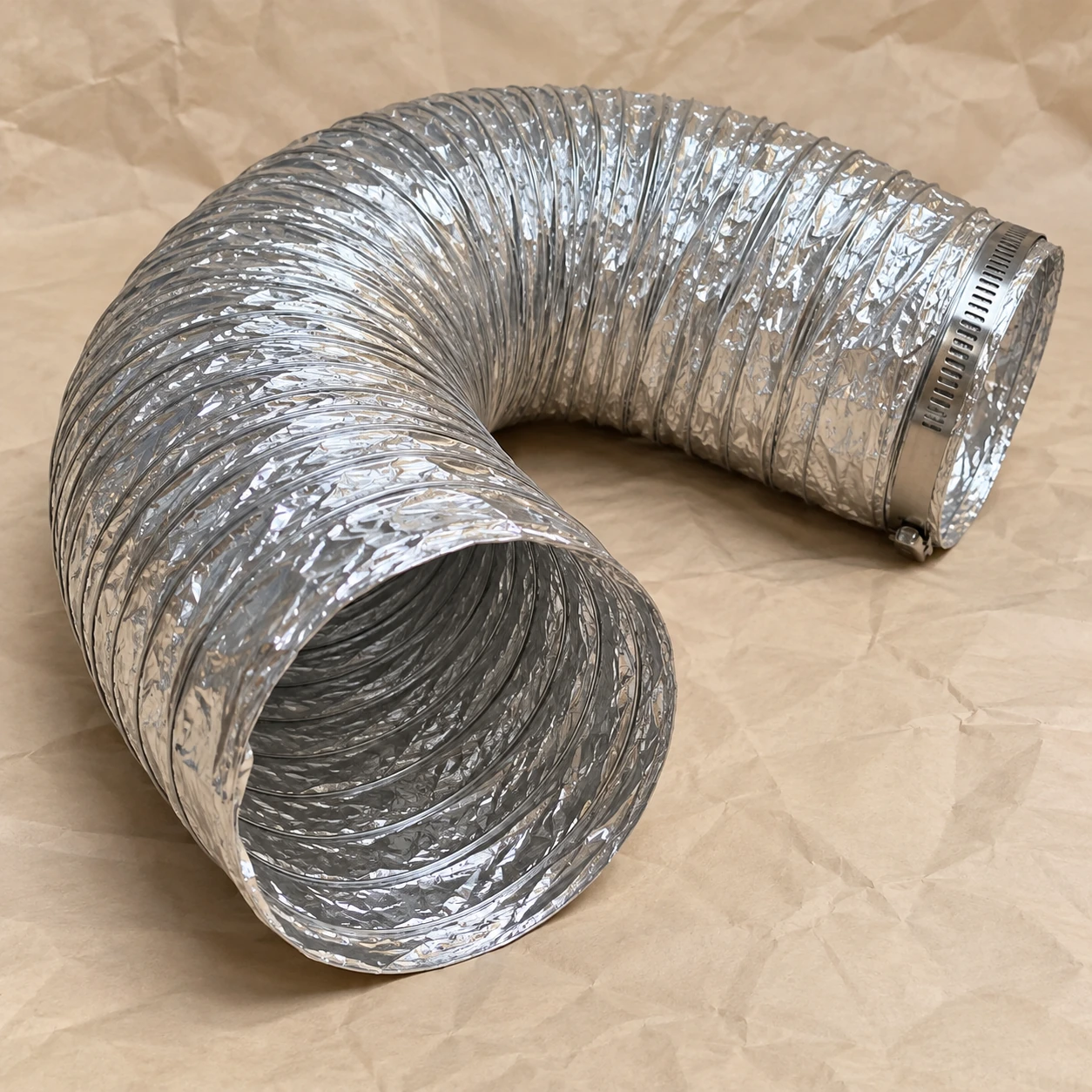
Flexible Air Ducts
8 inch flexible air duct
| Brand | shengtongJH |
|---|---|
| Nominal bore | 8 in = 203.2 mm; commonly designated 203 mm |
| Neighbouring options | 6 in / 8 in / 10 in by branch selection |
| Collar interface | Match actual spigot; check compatibility with nominal 200 mm systems |
| Supply length | 10 m fully extended pack or individual cut pieces |
| Liner construction | Wire-supported aluminium/polyester laminate |
| Insulation | Bare ventilation duct or selected insulated version |
| 25 mm insulated envelope | Approximately 253 mm outside diameter before accessories |
| Jacket option | Sealed foil laminate vapour jacket |
| Branch accessories | Collar, clamp, closure materials and supports |
| Air duty | General ventilation, supply or return within the specified rating |
| Installation limits | Temperature, pressure and bend requirements of the selected product |
Do not select the outlet airflow from bore alone. Use the route length, fittings, terminal resistance and available system pressure.
Branch lengths, jacket, insulation and connection kits can be customized to the outlet layout and installation conditions.
8 inch flexible air duct is a nominal 203.2 mm connection used for ordinary air-distribution branches. A sensible selection links the outlet requirement to the branch route so that installation convenience does not undermine airflow or maintenance access.
Start at the outlet requirement
A terminal should receive the airflow needed by the space or process area it serves. The branch diameter is chosen as part of the route that delivers that air. Two outlets with the same connection size can behave differently if one has a short clear approach and the other sits behind a long, sharply bent flexible run.
For a new branch, coordinate the take-off position with the ceiling and terminal layout early. A conveniently placed take-off reduces the amount of flexible material needed and leaves more room for other services. It also makes the route easier to inspect later.
Terminal connection
Match the collar behind the terminal, not the visible grille face. Keep the connection accessible and provide a sound mechanical joint before closing the insulation and jacket around it.
Branch balancing
Use a suitable balancing device where the air-system design requires one. Crushing or twisting the hose is not a controlled way to adjust flow and makes later fault-finding more difficult.
Service coordination
Route the branch clear of lighting access, sharp suspension components and removable ceiling panels. The duct should not become the obstacle that every maintenance visit pushes aside.
Keep airflow and sound questions separate
A flexible connection may change how vibration or sound travels, but ordinary foil duct is not automatically an acoustically rated attenuator. If outlet noise is a concern, identify whether it comes from excessive air velocity, a restrictive terminal, fan sound or the installation route. An acoustically selected duct or separate silencer may be appropriate, with its own performance data. Buying a thicker-looking hose without identifying the noise source can leave the original problem unchanged.
When ordering several branches, list each required connection length and the common accessories. This helps avoid excessive spare hose being left coiled above every outlet.
Branch lengths, jacket, insulation and connection kits can be customized to the outlet layout and installation conditions.