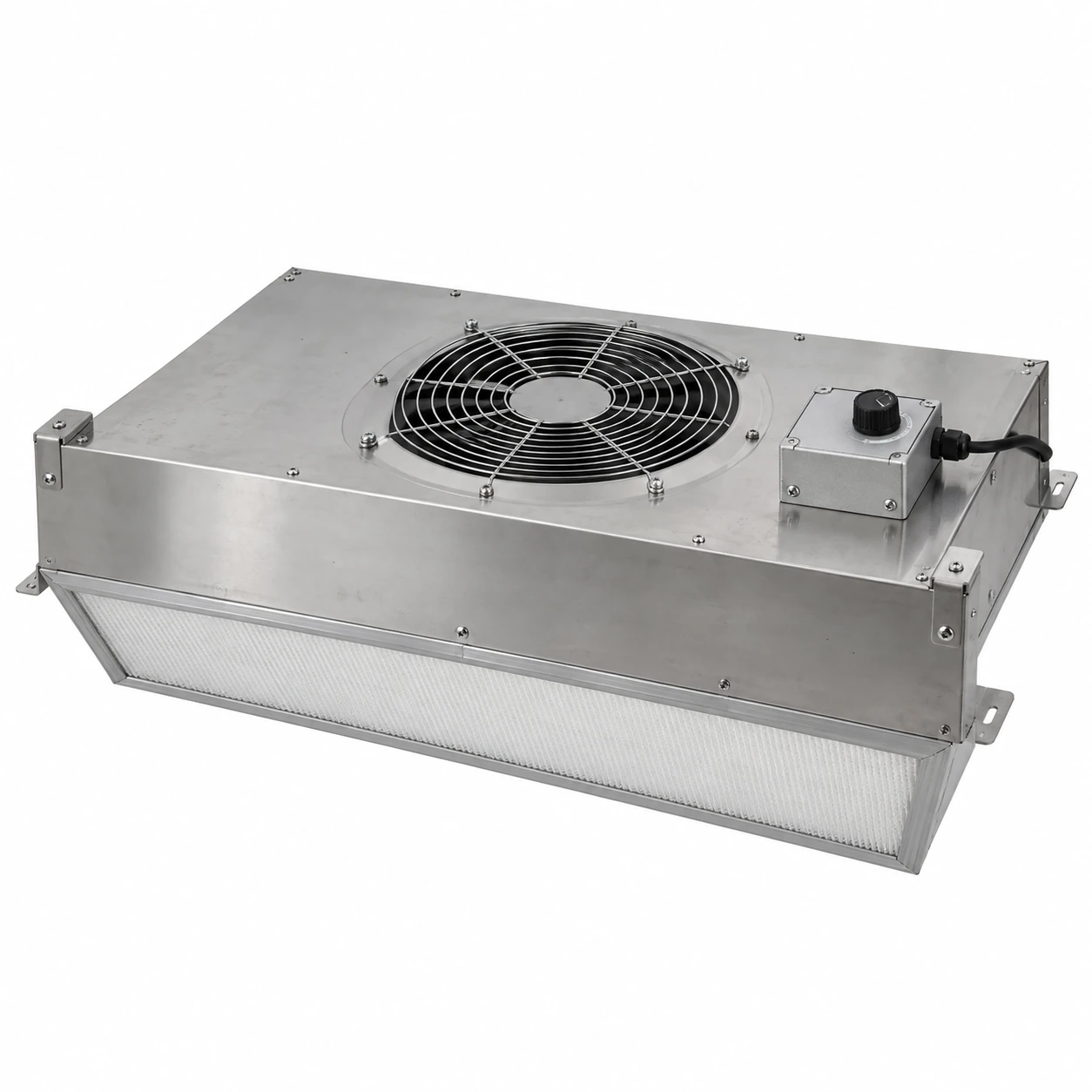
Fan Filter Units & Air Terminals
ffu fan filter unit
| Brand | shengtongJH |
|---|---|
| Equipment format | Independently powered ceiling or frame module |
| Housing W × D × H options | 575 × 575 × 320 / 1175 × 575 × 320 / 1175 × 1175 × 320 mm |
| Matched filter W × D × H | 570 × 570 × 70 / 1170 × 570 × 70 / 1170 × 1170 × 70 mm |
| Housing material | Galvanized steel; stainless steel option |
| Final filter | Selected H13/H14 HEPA panel |
| Drive alternatives | AC fan with compatible adjustment; EC fan with matched control |
| Supply | 220–240 V, 50 Hz; selected components must match site power |
| Control modes | Local speed setting or coordinated group command |
| Status options | Run/fault indication; airflow feedback by specification |
| Service isolation | Accessible electrical isolation and maintenance access |
| Operating setpoint | Established from measured airflow at the agreed duty |
A speed command is not an airflow measurement. Monitoring and automatic compensation are available only when included in the specified control configuration.
Controls, monitoring, operating groups and enclosure dimensions can be customized to the work zone and production routine.
An FFU fan filter unit allows the fan and final filter serving a work zone to operate as one module. Clear control settings help operators keep that module useful throughout daily production.
Make the normal operating state clear
Operators need to know whether the unit is running, whether its setting is correct and when a fault requires attention. A simple local controller can be suitable for a small work zone if its approved position is identifiable. Unmarked adjustment knobs invite changes that make performance difficult to repeat.
For a bank of units, a shared start command can simplify operation while still allowing individual balancing. Keep the location of each module associated with its control identity. A fault message is useful only when maintenance staff can find the affected unit.
Start-up
Define the required run condition before the sensitive process begins. A room or enclosure may need a project-specific recovery period; the fan starting does not prove that the area is ready.
Production
Keep inlets, outlets and returns clear. If equipment moves under the unit, assess the new air path instead of relying on an unchanged speed setting.
Interruption
Agree the restart behaviour after power loss and how staff are notified of stopped units. Automatic restarting may be appropriate in some installations but must fit the process and electrical design.
Know what the controller measures
A speed-control signal commands the drive; it does not prove the resulting airflow. Filter loading or a restricted intake can reduce output at the same command. A constant-airflow arrangement needs suitable feedback and sufficient fan operating margin, and should not be assumed from the presence of an EC motor alone.
Where monitoring is necessary, choose a meaningful signal and a documented response. Filter pressure, airflow and motor status answer different questions. Avoid an alarm arrangement that indicates only electrical power while a blocked air path goes unnoticed.
Keep service settings recoverable
Record the accepted operating settings and measurements after commissioning. Following filter replacement or controller work, restore the required airflow and check the affected zone. Routine control records help avoid trial-and-error adjustment each time a component is replaced. They also make a staged expansion easier to coordinate with the existing units.
Controls, monitoring, operating groups and enclosure dimensions can be customized to the work zone and production routine.