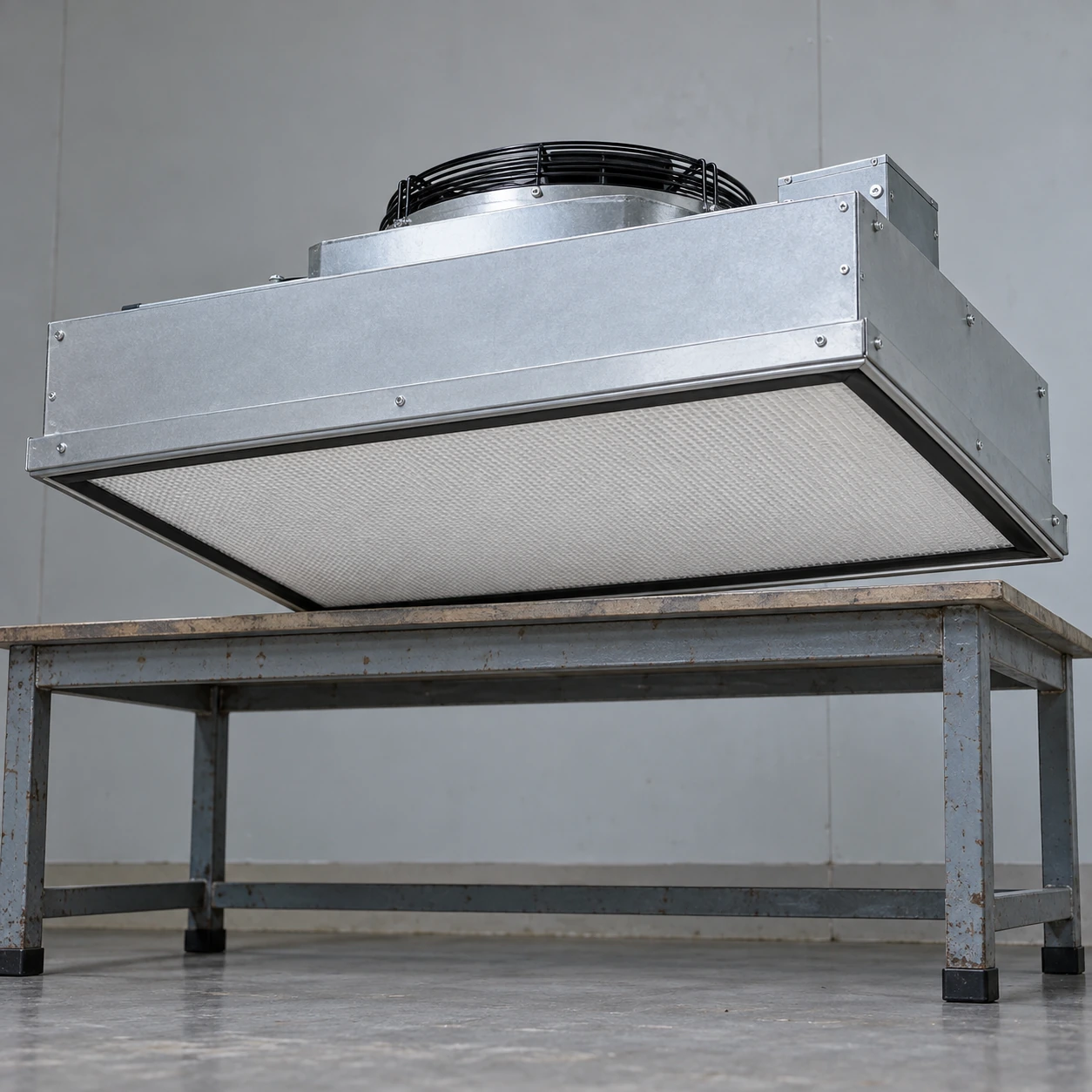
Fan Filter Units & Air Terminals
fan filter unit hepa
| Brand | shengtongJH |
|---|---|
| Assembly | Fan housing with replaceable HEPA final filter |
| Housing W × D × H options | 575 × 575 × 320 / 1175 × 575 × 320 mm |
| Filter W × D × H options | 570 × 570 × 70 / 1170 × 570 × 70 mm |
| Filter selection | H13 or H14 with supplied-item test documentation |
| Seal selection | Gasket seat or compatible gel/knife-edge assembly |
| Housing material | Galvanized steel; stainless steel option |
| Fan drive | AC or EC with matched control |
| Electrical supply | 220–240 V, 50 Hz; other supply by specification |
| Test provisions | Aerosol introduction and sampling connections where required |
| Adjustment | Accessible airflow control during commissioning |
| Replacement access | Room-side or upper access, matched to housing design |
Test connections and replacement direction must be specified with the housing. Installed testing follows the process requirements and selected test method.
Filter interfaces, test ports, maintenance access and enclosure dimensions can be customized to the application and verification requirements.
A fan filter unit HEPA installation must preserve the final filter from delivery through commissioning. Correct seating and suitable test access help turn a filter specification into a dependable installed air boundary.
Design for the check before installation
If the process requires installed HEPA integrity testing, provide the necessary access while selecting the equipment. The test arrangement must allow suitable upstream challenge conditions and access to the downstream filter face and perimeter. Adding a random port later does not ensure that the test conditions are valid.
Agree the applicable method and acceptance criteria with the party responsible for qualification. Keep the selected filter identity, factory documentation and installed test record connected. They establish different parts of the evidence and should not be treated as interchangeable certificates.
Install without damaging the filtration boundary
- Prepare the location. Complete dusty overhead work and clean the accessible seating surfaces before opening the final filter packaging.
- Inspect and place. Check the frame, media protection and seal. Lift the filter by its frame and seat it in the designed orientation.
- Secure evenly. Apply the intended retention method without forcing a distorted frame into place. Keep the sealing contact clear.
For gasket designs, the contact surface and compression matter. For gel-seal designs, the matching knife edge and gel condition matter. The two arrangements should be ordered as compatible assemblies rather than mixed because their outline dimensions happen to match.
Balance airflow separately
Check the operating airflow with the final filter fitted and the surrounding system running as intended. A controller position carried over from another unit may not deliver the same result. Use the agreed measurement procedure and document the setting.
Assess any leakage correctly
An installed check can identify leakage associated with media, the frame or the seal. A low pressure reading does not prove integrity. Investigate a failed result against the selected assembly and test method instead of masking a suspect perimeter with improvised repairs.
Preserve the record for the next service
Record filter identification, location, airflow condition and the outcome of required checks. After replacement or work that disturbs the seal, repeat the relevant verification before returning the protected process to service. This makes maintenance traceable and reduces uncertainty when the next filter is ordered.
Filter interfaces, test ports, maintenance access and enclosure dimensions can be customized to the application and verification requirements.