Fan Filter Units & Air Terminals
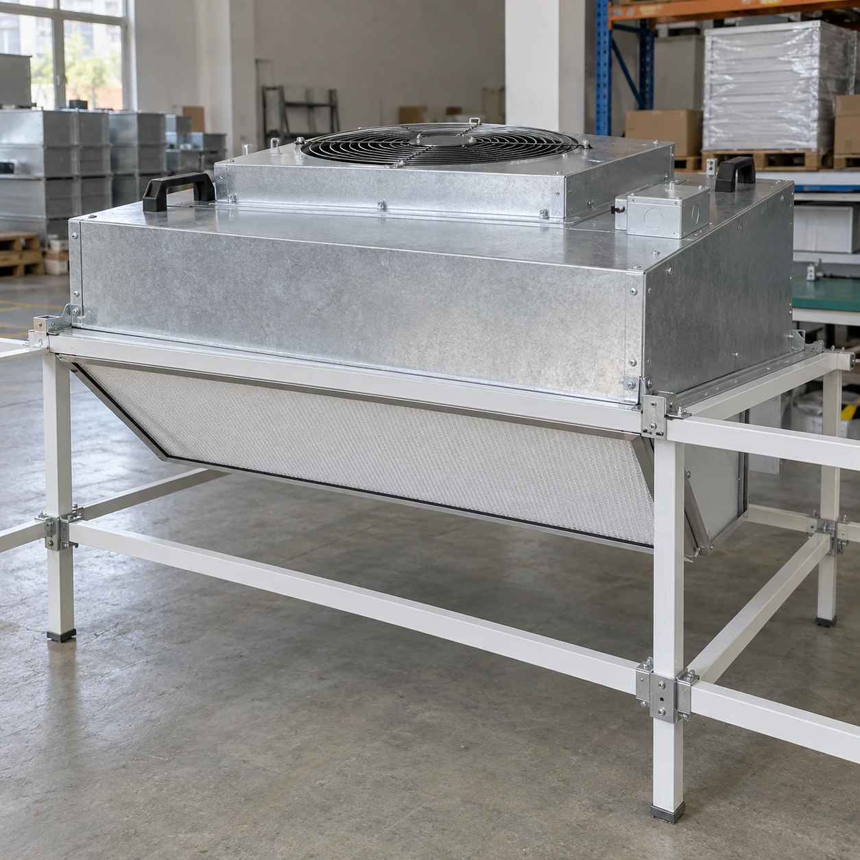
fan filter unit for clean room
| Brand | shengtongJH |
|---|---|
| Application | New industrial controlled-room or local-enclosure supply |
| Housing W × D × H | 575 × 575 × 280 / 1175 × 575 × 280 / 1175 × 1175 × 280 mm |
| Matched filter W × D × H | 570 × 570 × 70 / 1170 × 570 × 70 / 1170 × 1170 × 70 mm |
| Housing options | Galvanized steel or stainless steel |
| Final filtration | H13 or H14 HEPA, selected against process requirements |
| Fan alternatives | AC or EC centrifugal drive |
| Supply | 220–240 V, 50 Hz; site-specific configuration available |
| Controls | Individual balancing; zone or central operation option |
| Installation | Matched ceiling grid or engineered support frame |
| Service selection | Top access or room-side replacement configuration |
| Commissioning provisions | Airflow adjustment and specified filter test access |
Module count and location require a room-specific airflow design. Unit size or HEPA grade alone does not determine the finished room classification.
Module sizes, ceiling interfaces, control zones and filter-service arrangements can be customized to the room layout and process.
Choosing a fan filter unit for a clean room begins with the process layout. The units should support the areas that need protection while fitting the ceiling structure, services and maintenance plan.
Mark the critical operations first
Locate the surfaces or products exposed during assembly, inspection or preparation. Identify nearby particle sources and the people or materials moving past them. This gives the ceiling layout a practical purpose: supplying the areas that require protection rather than filling openings uniformly without regard to the process.
Allow for the actual machine height, service positions and lighting. A large overhead service can block air from reaching a bench. Moving a module slightly on the drawing may be more effective than increasing the capacity of an obstructed one.
Supply placement
Arrange the outlets around the exposed work and intended air direction. Coordinate modules with lights, sprinklers and other services without compromising their required access or function.
Return placement
Provide a clear route out of the protected zone. A return hidden behind stored cartons or production equipment can undermine the planned air pattern.
Maintenance route
Check how filters and fan modules will be removed. Room-side service may be useful where ceiling access is restricted, but it must suit the chosen housing.
Separate recirculation from building duties
Coordinate outside air, cooling, humidity control and exhaust with the HVAC design. FFUs can provide local filtered recirculation while other equipment handles those duties. Door operation and leakage affect room pressure and should be considered in normal production conditions.
Make future changes manageable
If expansion is likely, identify spare supported locations and the control capacity required for them. Seal unused openings appropriately. Future space is useful only if the surrounding supply, return and conditioning systems can support the added load.
Specify the acceptance conditions
Before purchase, define which filter documents and installed measurements are needed. Distinguish a filter integrity check from airflow balancing and room particle testing. State the relevant operational condition so acceptance is connected to how the space will actually be used.
For sourcing, a coordinated ceiling layout and process requirement are more useful than a room area alone. They allow shengtongJH to match equipment formats and interfaces while preserving access, coverage and the intended control arrangement.
Module sizes, ceiling interfaces, control zones and filter-service arrangements can be customized to the room layout and process.