Fan Filter Units & Air Terminals
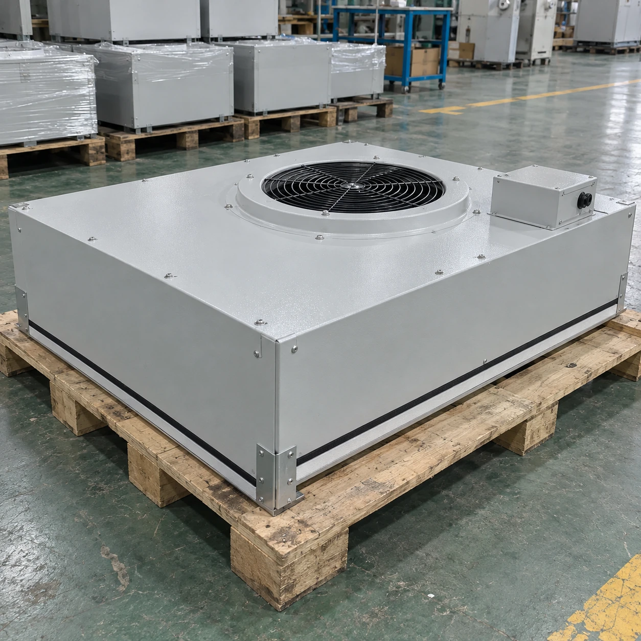
fan filter unit ffu
| Brand | shengtongJH |
|---|---|
| Unit format | Ceiling or frame-mounted fan/filter assembly |
| Housing W × D × H | 575 × 575 × 320 / 1175 × 575 × 320 mm |
| Matched filter W × D × H | 570 × 570 × 70 / 1170 × 570 × 70 mm |
| Housing | Galvanized steel or stainless steel |
| Filter selection | HEPA H13/H14 with compatible frame and seal |
| Inlet arrangement | Open plenum; duct collar by separate configuration |
| Drive | AC or EC fan with compatible controller |
| Supply connection | 220–240 V, 50 Hz; confirm local electrical requirements |
| Seal arrangement | Continuous gasket or matched gel-seal construction |
| Control interface | Local adjustment or coordinated group control |
| Installation support | Purpose-designed grid/frame; independently supported where required |
Open-plenum and duct-connected versions require different inlet and pressure selections. The mounting design must suit the supplied assembly.
The housing, support detail, inlet connection and control interfaces can be customized to the installation and process requirements.
A fan filter unit FFU is a compact equipment assembly, but installing several modules creates a coordinated air-distribution system. Structural, sealing and electrical interfaces deserve the same attention as the filter grade.
The ceiling is an equipment interface
A grid opening must carry the intended load and locate the unit without distorting its housing. The support detail should allow the filter to seat evenly. Do not rely on a decorative ceiling panel to carry equipment unless the supporting system is designed for it.
Plan how the unit will be lifted into position and later removed. A module can fit the final opening yet be impossible to pass through the access route. Above-ceiling services and the intended filter withdrawal direction should be resolved on the layout.
Keep the air boundary continuous
Unsealed penetrations around the module can admit unfiltered air to the protected area. The housing perimeter, filter seat and adjoining panels need compatible joints. Compression gaskets must contact a suitable surface; a gel seal needs the matching knife-edge arrangement.
Clamp the filter as its construction requires. Extra force does not repair a damaged frame and may create new leakage by distortion. Keep cables and labels out of the sealing contact.
Coordinate three connections before delivery
- Air connection. Establish whether the fan draws from a shared plenum or a defined duct. Check inlet clearance and the pressure condition at the connection.
- Electrical connection. Match supply, isolation, protective arrangements and controller compatibility. Leave connectors and service points accessible.
- Control connection. Define which units run together, which are independently adjustable and what happens after a power interruption.
A mixed installation with unrelated controller types can be difficult to balance and maintain. Record a unit location and control identity on the equipment schedule so settings can be traced to the correct work zone.
Commission the assembled system
Once the modules, enclosure and return routes are complete, check the delivered airflow and any required installed filter integrity. Changes to doors, exhaust or neighbouring units can affect the operating condition. A satisfactory test of one module before installation does not establish the performance of the finished room.
For staged projects, agree where future modules connect and how spare openings remain sealed. This reduces later disruption without pretending that unused ceiling space already provides clean-air capacity.
The housing, support detail, inlet connection and control interfaces can be customized to the installation and process requirements.