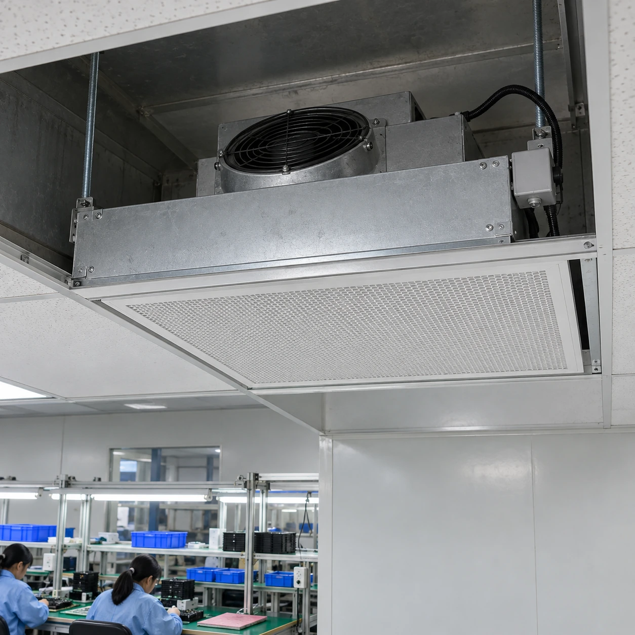
Fan Filter Units & Air Terminals
fan filter unit cleanroom
| Brand | shengtongJH |
|---|---|
| Housing options W × L × H | 615 × 615 × 265 / 1175 × 575 × 265 / 1175 × 1175 × 265 mm |
| Filtration | H13 / H14 final filter to selected duty |
| Motor option | AC speed control or compatible EC control |
| Casing | Galvanized steel; stainless steel option |
| Electrical supply | 220 V, 50 Hz; alternatives to offered configuration |
| Control layout | Individual or grouped operation with identifiable unit positions |
| Monitoring options | Airflow feedback, filter differential pressure or fault signal |
| Service access | Top-side or room-side filter replacement |
| Operating records | Unit identity, setpoint, airflow and maintenance date |
| Application coordination | Room return path, occupancy, process equipment and exhaust |
Operating airflow, control settings and alarm thresholds are established for the selected installation. Generic settings do not demonstrate room cleanliness.
Unit dimensions, monitoring and control groups can be customized to the production schedule and maintenance arrangements.
For a fan filter unit cleanroom installation, commissioning connects the selected equipment to actual room performance. The operating settings, return paths and filter condition need a clear baseline so later changes can be understood.
Create a baseline that maintenance can use
Record each unit's position and operating setting after the room has been balanced. Include the measurement method and relevant operating condition. A speed percentage by itself does not describe delivered airflow, and the same percentage may produce different results with a different motor or filter.
Keep the commissioning record with the replacement-filter schedule. When a problem appears later, these records help distinguish an altered setting from filter loading or a change elsewhere in the room.
Check the air route
Keep intakes and returns unobstructed. If airflow changes after new shelving or equipment arrives, review the room arrangement before assuming every filter needs replacement.
Read indicators in context
A running light shows an electrical state, not necessarily useful delivery. Pressure readings also depend on where the connections are located. Label what each indicator measures so operators do not confuse filter resistance with room pressure.
Control interventions
Restrict casual speed changes and record authorized adjustments. Increasing a setting to overcome a blockage may disturb balance and conceal a service issue that should be corrected.
Respond to reduced airflow systematically
Review the power and control status, intake condition and filter pressure trend. Look for damaged seals or an incorrect replacement panel where the problem follows maintenance. For duct-connected equipment, include upstream air supply in the investigation. The fan and filter are only part of the circulation path.
After corrective work, restore the intended duty and complete the checks required by the process. Replacing a filter should not end with simply turning the fan back on.
Keep responsibilities clear
Operating procedures should identify who can alter settings, what triggers maintenance and how a failed unit is reported. Where reduced-speed or shutdown periods are proposed, assess the effect on the process and room condition before adoption. shengtongJH coordinates equipment options and documentation for that operating plan; a unit supply does not itself constitute room qualification.
Unit dimensions, monitoring and control groups can be customized to the production schedule and maintenance arrangements.