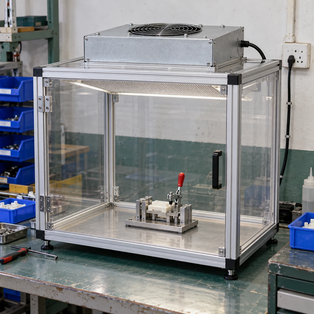
Fan Filter Units & Air Terminals
equipment fan filter unit
| Brand | shengtongJH |
|---|---|
| Equipment format | Compact overhead fan/filter assembly for a machine or enclosure |
| Housing footprint options | 615 × 615 / 1175 × 575 mm; custom footprint to equipment drawing |
| Housing depth | 265 mm construction; compact versions require fan and clearance review |
| Filter grade | H13 / H14 selected for the protected process |
| Mounting | Bolted support frame or equipment canopy interface |
| Housing material | Galvanized steel or stainless steel by environment |
| Fan and controls | Speed-controlled AC or EC fan; machine enable signal where specified |
| Electrical supply | 220 V, 50 Hz; destination-compatible alternative |
| Discharge protection | Filter-face protective grille where suitable |
| Integration inputs | Machine opening, heat sources, moving parts and maintenance route |
The mounting frame and surrounding equipment are project interfaces. Filtration does not provide hazardous-process containment or establish whole-room cleanliness.
Footprint, mounting interface, controls and discharge arrangement can be customized to the machine and exposed work area.
An equipment fan filter unit supplies filtered air to a machine enclosure or defined work zone. This local approach can protect exposed parts without treating every part of a production hall to the same requirement.
Protect the exposed operation
Identify where particles can reach the product: an assembly station, an optical handling point or an open machine transfer. Position the filtered supply so it serves that location without being blocked by the machine frame, tooling or an operator's hands.
A small enclosure can concentrate useful clean-air delivery, but it needs a defined outlet or return path. A tightly enclosed box with insufficient relief can restrict flow; a large open face can allow surrounding drafts to dominate. The enclosure geometry is part of the selection.
Work with machine movement
Loading doors, robot travel and lifting guards change the air boundary. Assess the normal production cycle rather than only the closed, idle machine. Keep the unit clear of movement envelopes and avoid locating the discharge where it carries particles from a dirty mechanism towards the product.
Heat from motors or process equipment can also disturb the intended airflow. If temperature matters, coordinate heat removal separately instead of expecting filtration to cool the enclosure.
Make service possible without dismantling production
Allow a safe filter withdrawal route and access to the fan and wiring. Protect delicate tooling below during replacement. A lower-profile assembly may help with headroom, but the internal air path and fan duty still need review.
Include isolation and restart behaviour in machine integration. An enable signal alone does not confirm actual airflow; use suitable feedback where the process depends on verified operation.
Understand the boundary of local filtration
This equipment is intended to support product protection from airborne particles. It is not a substitute for extraction where a process releases solvent vapours, hazardous dust or other harmful emissions. Those applications need a separately assessed containment and exhaust arrangement.
Provide the equipment drawing and process sequence so shengtongJH can coordinate the housing and filtered-air supply around the real working zone. The result should be evaluated with the machine operating and its normal access movements in use.
Footprint, mounting interface, controls and discharge arrangement can be customized to the machine and exposed work area.