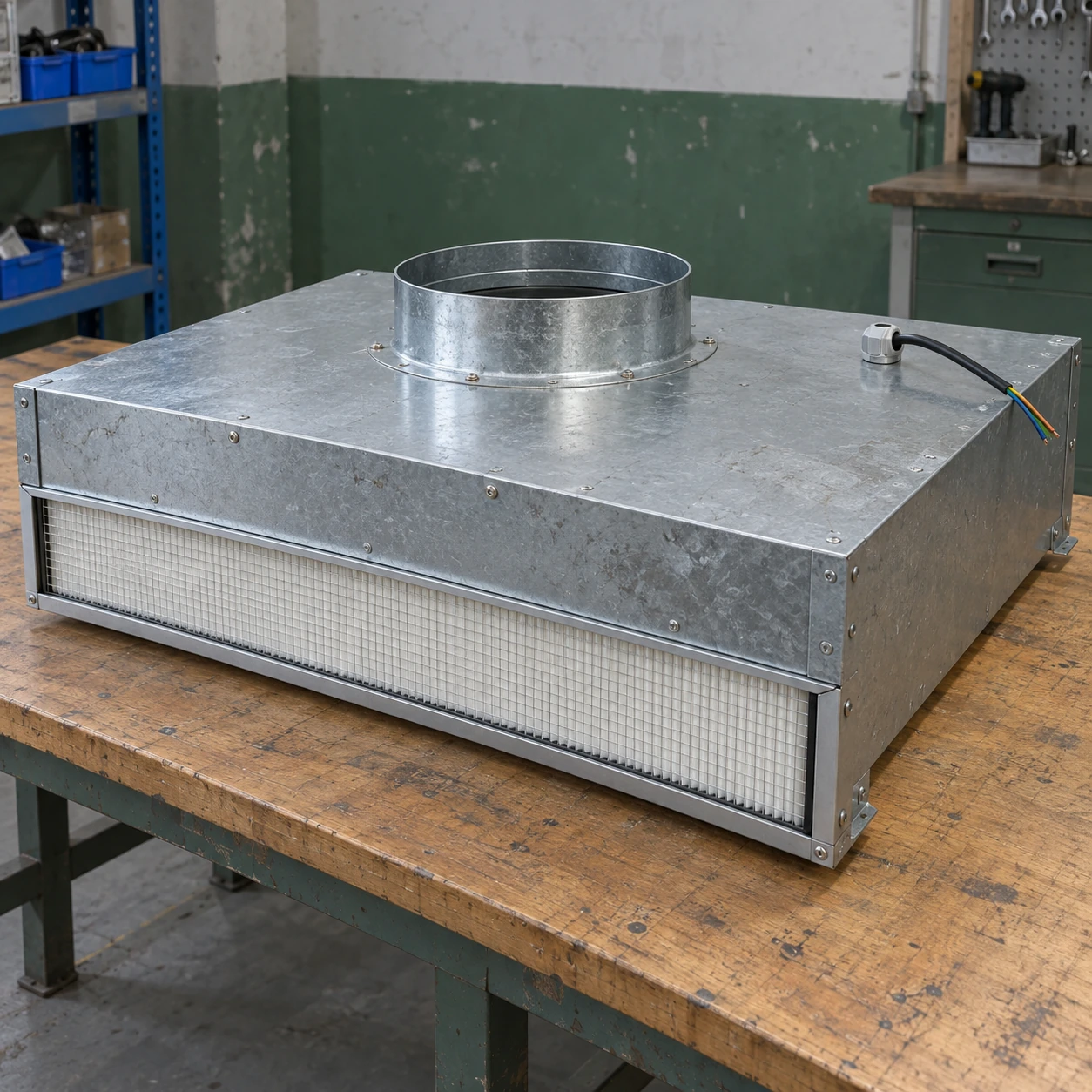
Fan Filter Units & Air Terminals
ducted fan filter unit
| Brand | shengtongJH |
|---|---|
| Housing size options W × L × H | 615 × 615 × 265 / 1175 × 575 × 265 mm, excluding duct connection |
| Inlet interface | Top duct collar sized for the approved airflow and duct connection |
| Filter selection | H13 / H14 with matched housing seal |
| Casing material | Galvanized steel; stainless steel option |
| Fan arrangement | Centrifugal fan selected against inlet conditions and final-filter resistance |
| Control input | Local adjustment or compatible EC external control |
| Inlet pressure duty | Allowed operating range from the selected assembly supplier |
| Power supply | 220 V, 50 Hz; other supplies matched to motor |
| Monitoring options | Inlet pressure access, airflow indication and filter pressure measurement |
| Service configuration | Room-side filter access or accessible top-service construction |
Body dimensions exclude the inlet connection and required service clearance. The allowable inlet pressure is unit-specific; fan performance must be checked with the upstream system.
Duct connection, housing dimensions, control signal and service arrangement can be customized to the ventilation layout.
A ducted fan filter unit connects a terminal fan and final filter to an upstream air supply. The upstream system and local fan must operate together; attaching a duct to a recirculating unit does not automatically create a suitable ducted terminal.
Two fans need one operating plan
The central supply fan moves air through the distribution system while the terminal FFU supplies its final-filter section. Excessive positive pressure at the FFU inlet can force excess flow through the terminal. An overly negative inlet can prevent the local fan from reaching its intended duty.
Specify the inlet conditions allowed by the offered unit and coordinate the upstream balancing device. Do not apply a free-air fan rating to the complete ducted installation.
Balance airflow and inlet pressure together
Commissioning should measure the terminal airflow and the pressure at its inlet. Changing only the FFU speed can mask a distribution problem or leave the unit operating outside its intended conditions. Adjust the upstream supply and local control according to the selected equipment's instructions.
Check the arrangement at the operating conditions the building will actually use. A terminal that works with all zones open may behave differently when upstream controls reduce flow elsewhere. Where variable-volume operation is required, agree the control relationship before selecting the unit.
Keep the connection serviceable
Support the duct independently so its weight does not distort the unit casing or sealing edge. Leave access for the electrical connection and any inlet prefilter. A short connection can still prevent filter or motor removal if it crosses the service opening.
Identify which items are supplied with the FFU and which belong to the duct installation, including balancing hardware and access points.
Condition the air upstream
The terminal filter does not replace cooling, heating or humidity control. Avoid conditions that allow condensation on the casing or filter, and assess incoming air quality before the final stage. Process exhaust and room-pressure control remain part of the wider system.
For procurement, provide the intended airflow, duct route, available pressure and control sequence. shengtongJH uses those interfaces to coordinate an appropriate ducted assembly rather than substituting a standard open-intake unit.
Duct connection, housing dimensions, control signal and service arrangement can be customized to the ventilation layout.