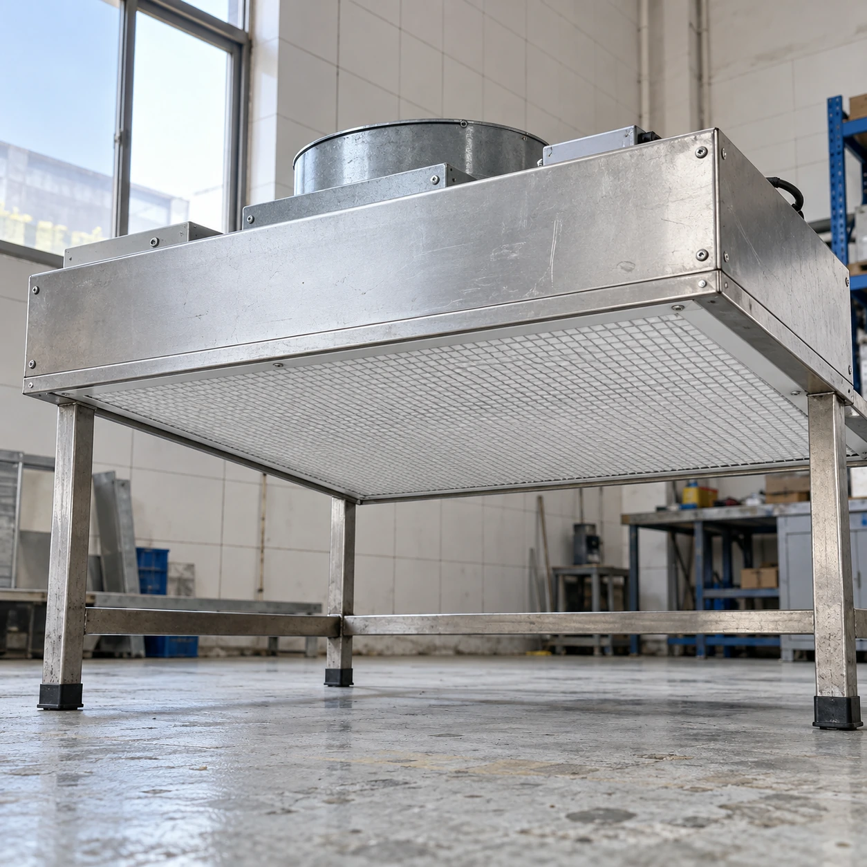
Fan Filter Units & Air Terminals
clean room hepa fan filter unit
| Brand | shengtongJH |
|---|---|
| Housing size options W × L × H | 615 × 615 × 265 / 1175 × 575 × 265 / 1175 × 1175 × 265 mm |
| HEPA grade options | H13 or H14 under EN 1822 |
| Filter classification basis | Performance at MPPS; corresponding filter test record required |
| Filter frame | Aluminium frame with continuous selected sealing interface |
| Seal selection | Gasket or gel seal in a compatible housing |
| Casing | Galvanized or stainless steel |
| Motor | Speed-controlled centrifugal fan; AC or EC selection |
| Electrical supply | 220 V, 50 Hz; other supplies to selected components |
| Testing access | Aerosol and sampling provision where specified for the selected assembly |
| Replacement access | Room-side or top-side method agreed before order |
A HEPA grade is a filter classification, not a room certification. Installed testing requirements, access and acceptance criteria must be specified for the project.
Filter grade, seal arrangement, test access and service direction can be customized to the process and maintenance conditions.
A clean room HEPA fan filter unit directs air through a final filter before it reaches the room. Its perimeter seal is as important as the media: air bypassing the filter can undermine the intended particle control.
The seal completes the filtration path
Air follows the available path. A damaged gasket, twisted seating frame or loose retaining point can create a route around otherwise suitable filter media. Check the complete contact surface and clamping arrangement rather than treating the filter label as proof that the installed unit is sound.
Gasket and gel-seal systems require different interfaces. Matching the filter's face dimensions does not make the two interchangeable. The selected panel must seat correctly without excessive force or distortion.
Before installation
Keep the filter protected until the work area is ready. Inspect the frame, media and sealing edge. Handle the panel by the frame and keep tools away from the pleats; a small handling defect may not be visible from the room below.
During fitting
Clean the contact surfaces and follow the assembly's retaining sequence. Uneven tightening can distort a frame rather than improve its seal. Ensure the airflow direction and filter position match the selected construction.
After replacement
Restore the specified airflow and complete the installed checks required by the process. Keep filter identity and maintenance records together so later investigations can distinguish a new panel from an older unit.
Specify the right evidence
EN 1822 classification evaluates performance at the most penetrating particle size. Avoid replacing that classification with a generic efficiency percentage at an unrelated particle size. Ask for the record corresponding to the supplied filter, not merely a media brochure.
Filter records and installed integrity assessment answer different questions. Where installed testing is needed, make access for aerosol introduction and sampling part of procurement.
Preserve performance in daily work
Protect the discharge face from impact, unsuitable cleaning and obstructing fixtures. Plan maintenance so debris from the ceiling void does not fall into the work zone. The FFU supports particle control; room classification also depends on air distribution, operational conditions and the wider facility design.
Filter grade, seal arrangement, test access and service direction can be customized to the process and maintenance conditions.