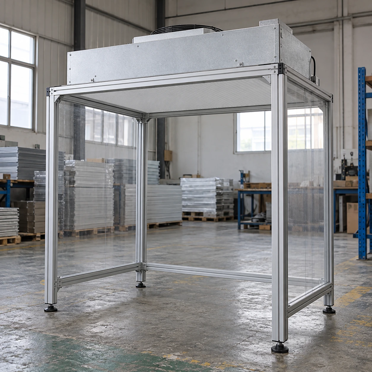
Fan Filter Units & Air Terminals
clean room ffu
| Brand | shengtongJH |
|---|---|
| Installation | Retrofit ceiling or supported local enclosure |
| Housing W × D × H | 575 × 575 × 280 / 1175 × 575 × 280 mm |
| Filter W × D × H | 570 × 570 × 70 / 1170 × 570 × 70 mm |
| Construction | Galvanized steel or stainless steel |
| Final filtration | H13 or H14 HEPA selected for the process |
| Fan control | Adjustable AC or EC drive |
| Electrical supply | 220–240 V, 50 Hz; other supply by component selection |
| Intake | Accessible plenum inlet with optional prefilter |
| Service direction | Above-ceiling or room-side arrangement selected before installation |
| Monitoring options | Airflow indication and filter pressure connections |
| Support and seal | Matched grid/frame and perimeter sealing detail |
Choose the actual housing depth and service direction after checking the existing ceiling void. Added FFUs do not independently establish a room classification.
Unit dimensions, maintenance access, controls and support details can be customized to the existing room and its operating conditions.
A clean room FFU can add localized filtered supply to an existing controlled area. A successful retrofit starts with the room constraints and contamination path, not simply the number of spare ceiling openings.
Find out why the existing area is underperforming
Particles can enter through poor door control, unsealed joints or process-generated dust. They can also remain near a workstation because a cabinet blocks the supply or return route. Adding more filtered air addresses some of these problems, but it does not remove their source automatically.
Walk the intended air path from the proposed outlet to the room return. Review the equipment in its operating position, including carts and open access panels. An apparently clear empty room may behave differently during production.
Use the ceiling void realistically
Existing ducts, beams and cable trays can obstruct the fan inlet or prevent filter access. Check available height over the full module footprint. A compact housing is only useful when it leaves enough clearance for intake and servicing.
Where above-ceiling access is limited, a suitable room-side replacement arrangement may reduce disruption. It must be part of the selected equipment design; an inaccessible top-change unit cannot be converted by improvising its retention hardware.
Balance the change with the rest of the room
Recirculating more air can improve local particle removal, but it does not necessarily increase outdoor-air supply or room pressure. Review the existing fresh-air, exhaust and pressure-control arrangements independently.
The fan adds heat and may change sound levels at occupied positions. Check that cooling capacity and operating controls remain suitable. Do not use more fan speed to compensate indefinitely for a blocked return or dirty prefilter.
Make the retrofit maintainable
Divide the work into areas that can be isolated and cleaned before the protected process resumes. Record the location, filter identity and normal setting of every added module. This avoids a later maintenance visit disturbing unrelated units or losing the original balance.
After installation, evaluate airflow and any required particle or integrity checks under the agreed room conditions. Compare the result with the problem the retrofit was intended to solve. A better reading at the filter outlet alone does not demonstrate improved protection at an obstructed work surface.
shengtongJH can source configurations that suit the existing ceiling, access route and process rather than requiring every room to adopt the same unit arrangement.
Unit dimensions, maintenance access, controls and support details can be customized to the existing room and its operating conditions.