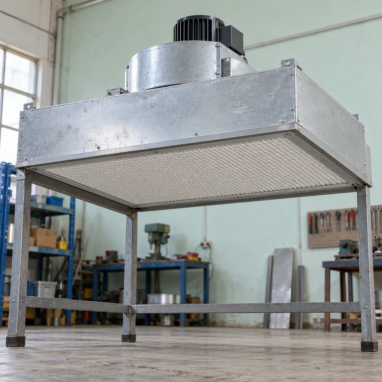
Fan Filter Units & Air Terminals
clean room fan filter unit
| Brand | shengtongJH |
|---|---|
| Housing size options W × L × H | 615 × 615 × 265 / 1175 × 575 × 265 / 1175 × 1175 × 265 mm |
| Housing materials | Galvanized steel; stainless steel option |
| Final filter | H13 or H14 to the specified EN 1822 classification |
| Airflow setting | Selected from the fan/filter duty curve and required ceiling coverage |
| Motor options | AC speed-controlled or EC motor |
| Power supply | 220 V, 50 Hz; alternative supply matched to the selected motor |
| Air intake | Open plenum intake with optional serviceable prefilter |
| Discharge | Downward filtered-air delivery through a protected filter face |
| Control | Local adjustment; group control where compatible |
| Service arrangement | Top-access or room-side filter replacement by selected construction |
Housing dimensions identify selectable constructions. Ceiling fit, filter size and delivered airflow must match the approved assembly; filter grade does not establish room classification.
Housing size, filter grade, control grouping and service access can be customized to the room layout and production process.
A clean room fan filter unit recirculates air through a final filter near the working area. Its useful performance depends on where the air travels after discharge: equipment, operators and return openings can change the protection that reaches exposed work.
Keep the return route open
A ceiling unit cannot create a useful circulation pattern if discharged air has nowhere to return. Cabinets positioned against return grilles, stored cartons below low-level returns and sealed-off ceiling spaces can all restrict the route. The result may be uneven airflow even while every fan appears to be running.
Plan supply positions and return openings together. Place the equipment layout on the same drawing so large machines do not block the intended path. Where a process is particularly sensitive, assess the flow around the exposed product rather than relying only on the average room air-change calculation.
People change the working conditions
Operators carry particles and disturb air as they move. A workstation that performs well while empty may behave differently with staff, trolleys and opening doors. Keep the clean-air route to critical surfaces as direct as the process allows, and avoid placing routine traffic between the supply and exposed work.
The required coverage also depends on particle generation. Adding more ceiling units is not always the first remedy; managing a dusty transfer operation or moving a return obstruction may address the source more effectively.
Separate filtration from room conditioning
The FFU provides local fan assistance and particle filtration. The wider HVAC arrangement still has to handle fresh air, heat, humidity and the balance between supply and extract. More recirculation alone will not resolve a hot machine area or an incorrect room-pressure relationship.
Identify process exhaust before specifying the unit quantity. An extract change can alter the room balance without any change to the FFUs themselves.
Set up the room for repeatable operation
After installation, record the operating settings and check the occupied arrangement as well as the empty room. Keep returns accessible for cleaning and prevent new shelving from obstructing them. Retain an FFU location schedule so filter replacements and future changes can be traced to the correct position. shengtongJH coordinates unit sourcing against this room and equipment information.
Housing size, filter grade, control grouping and service access can be customized to the room layout and production process.