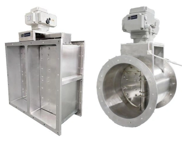
Airtight Isolation Dampers
Biosafety Airtight Damper
| Specification | Configuration options |
|---|---|
| Duct format | Circular or rectangular |
| Body material | 304 or 316 stainless steel |
| Connection size | Custom diameter or W × H in mm to match the duct |
| Assembly depth | Configured for blade, seal and installation clearance |
| Operation | Actuated operation with local control |
| Control integration | Ventilation-system interlock |
| Installation | Flanged duct connection |
| Customization | Interface dimensions, actuator position and control arrangement |
Dimensions and configurations can be customized for your application.
A duct-mounted isolation device for controlled ventilation systems. The damper closes the air path when isolation is required, with its body, seal, actuator and control sequence selected as one assembly.
Close the air path at the required boundary
A ventilation system may need to isolate a branch, filter section or room connection during servicing, decontamination or an abnormal operating condition. An airtight damper provides a defined closing point in that duct route. Its position should follow the part of the system that must be isolated, rather than simply the nearest convenient straight length of duct.
Isolation and normal airflow balancing serve different purposes. A partially closed balancing damper adjusts resistance; a containment isolation duty depends on the closed blade, seat, body and connecting joints working together. The selected assembly must address the pressure and direction of leakage that matter to the installation.
Match the shape to the available installation
Circular and rectangular formats connect to different duct arrangements. Check the clear air opening as well as the flange outline: transitions, neighbouring equipment and supports affect the actual space required. The actuator can project beyond the duct body, so its orientation needs to be shown on the installation drawing.
Leave room to access the drive, position indication and seals. A damper hidden above a fixed ceiling or directly against a filter housing can be difficult to inspect even when the duct connections fit correctly. Coordinate access panels and removal space before enclosing the services.
Specify the complete pressure boundary
Closed-blade leakage and leakage through the outer casing are different checks. State the required test pressure, direction, acceptance criterion and test method when defining an isolation duty. Include flange gaskets and site joints in the installation review; a well-sealed blade cannot compensate for leakage around its mounting.
Connect the damper action to the fan sequence
Normal operation
The ventilation system needs to know when the required air path is available. Coordinate actuator commands and position feedback with fan operation so an assumed open path is not treated as a proven open path.
Isolation request
Define which fans, neighbouring dampers and process permissions change when this damper closes. The sequence must account for the pressure change created by blocking a duct, particularly where supply and extract systems serve the same room.
Loss of services
Agree the required position after a loss of electricity, control signal or actuator supply. Fail-open, fail-closed and hold-position behaviour are different actuator arrangements and must follow the system risk assessment.
Build maintenance into the specification
Seal material and exposed metal must be compatible with the air stream and any decontamination chemistry. Keep cleaning access, seal replacement and actuator servicing practical. If the damper serves a filter installation, review the isolation boundary together with filter testing and maintenance access.
For selection, provide the duct drawing, operating pressure, required isolation condition and the available controls. Connection dimensions, material, actuator orientation and control interfaces can be customized for your ventilation system. Discuss the isolation requirement.