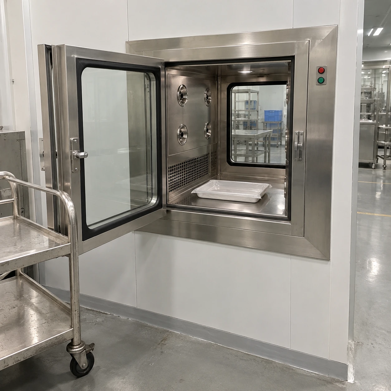
pass box air shower
Product specifications
| Spec | Configuration |
|---|---|
| Transfer type | Material pass box with directed filtered-air jets and separate loading and receiving doors. |
| External planning envelopes | Bench transfer: 800 × 800 × 1000 mm Larger components: 1200 × 1000 × 1400 mm Floor-level transfer: 2000 × 2000 × 2100 mm Illustrative external W × D × H; final dimensions follow the approved configuration drawing. |
| Usable transfer space | Internal W × D × H selected around the largest closed container, support and jet clearance; door opening specified separately. |
| Chamber material | Cleanable stainless interior, nozzle fittings and removable supports appropriate to the object. |
| Load support | Shelf or tray arrangement that keeps the load stable and allows the intended surface exposure. |
| Jet layout | Directed side and optional upper nozzles positioned to avoid displacing fragile loose items. |
| Filtered circulation | Prefilter, documented final particle filter and return path kept clear around the load. |
| Transfer controls | Door interlock, adjustable air cycle and visible completion status before receiving-side retrieval. |
| Handling interface | Bench mounting or a separately designed floor-level wheel path, ramp and clear load opening. |
Load space, supports and door arrangement can match your containers, transfer equipment and installation opening.
Transfer an object through the wall while keeping the handling sequence separate from personnel entry.
A pass box handles goods.
A pass box air shower is a material-transfer chamber with a filtered-air particle-removal stage. Opposing doors let staff load from one side and retrieve from the other. It is selected around the object, its packaging and the way it is handled; it is not a miniature personnel shower.
A static pass box establishes a controlled opening without an active air-cleaning cycle. A ventilated pass box provides filtered airflow. An air shower version adds directed jets for suitable exposed surfaces. These arrangements are different, so “filtered” and “air shower” should not be used interchangeably in the equipment schedule.
The object decides the airflow.
A smooth tray, a sealed component container and a bag with deep folds do not present the same surface. Jets cannot reach the underside of a box resting directly on a solid shelf. A support arrangement can expose more surface, but it must also keep the load stable and be easy to clean.
Fragile loose parts and open powders can be displaced by jets. Use an appropriate closed container or a different transfer procedure rather than increasing air speed by default.
Build the cycle around loading and retrieval.
- Prepare outside: remove unsuitable outer packaging and keep the receiving chamber free of debris.
- Load without blocking returns: leave the agreed clearance around the object and close the loading door.
- Run the selected cycle: the door state and active-air stage follow a defined control sequence.
- Retrieve from the receiving side: allow the process to finish before unloading and prevent both doors being opened together.
Adjustable cycle timing, door interlock, a visible status indication and accessible filter panels are useful configuration options. UV, where separately requested, is not a substitute for a proven cleaning or disinfection process and should not be assumed to reach shadowed surfaces.
Dimension the load, then the enclosure.
Bench transfer
800 × 800 × 1000 mm external is an illustrative W × D × H planning envelope for small closed items. Specify usable chamber space around the largest container independently.
Larger component transfer
1200 × 1000 × 1400 mm external is a planning example for a larger handling task. Check shelf load, reach distance and lifting height.
Floor-level trolley transfer
2000 × 2000 × 2100 mm external is a planning example for discussion where a trolley enters the chamber. Wheel path, clear doorway, ramp slope and the loaded height are separate dimensions.
These configuration planning examples establish a starting space for the load and handling method. Confirm internal clear width, depth, height and door opening on the selected drawing; fan and filter cabinets consume part of the external envelope.
Compare personnel entry ↗Custom configurations are available to suit the installation space, object size, transfer equipment and application.