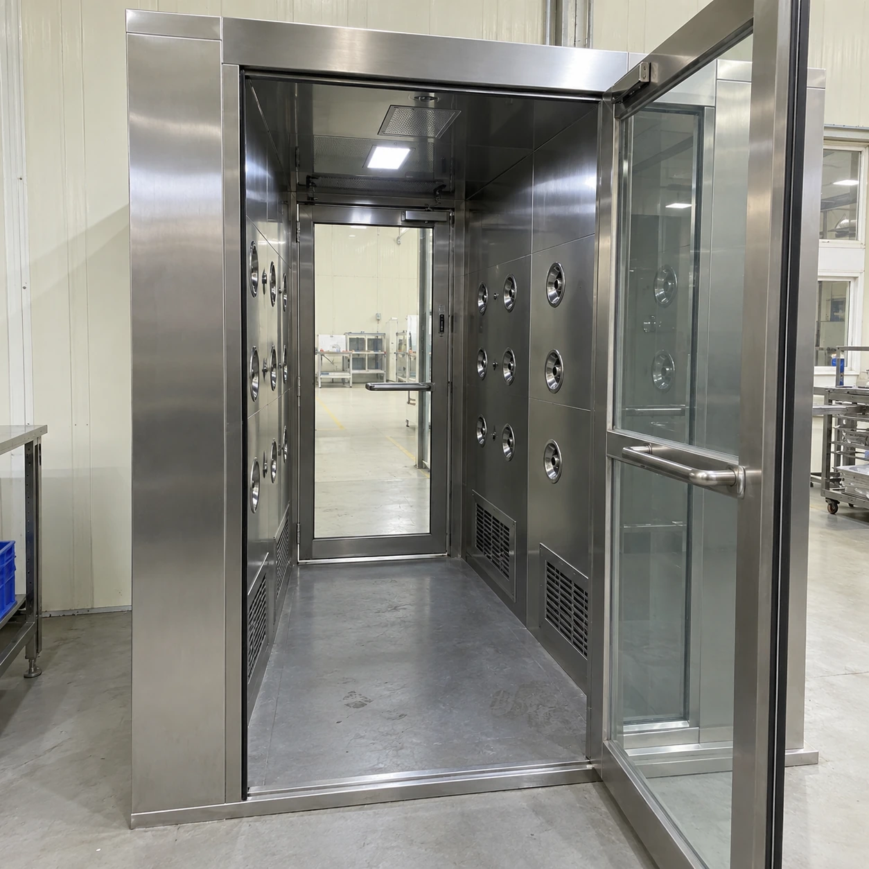
air shower chamber for cleanrooms
Product specifications
| Spec | Configuration |
|---|---|
| Chamber format | Enclosed personnel chamber with separate doors, nozzle walls and lower air returns. |
| External chamber sizes | Short: 1400 × 1000 × 2100 mm Intermediate: 1400 × 1500 × 2100 mm Extended: 1400 × 2000 × 2100 mm Reference W × D × H; final dimensions follow the approved configuration drawing. |
| Internal W × D × H | Short reference: 800 × 910 × 1980 mm Intermediate reference: 800 × 1410 × 1980 mm Extended reference: 800 × 1910 × 1980 mm |
| Clear door reference | 760 × 1960 mm, W × H; alternative doorway geometry selected for the intended users. |
| Occupied geometry | Standing and turning areas drawn clear of cabinet projections, door movement and return grilles. |
| Jet arrangement | One-sided or opposing-side nozzle banks; upper blowing where appropriate to the occupied layout. |
| Interior construction | Stainless lining or full stainless enclosure, flush lighting and accessible grille covers. |
| Filtration and access | Replaceable prefilter and documented final filter; side-access panels where the maintenance route permits. |
| Cycle sequence | Adjustable duration, door interlock, countdown and defined emergency-release behaviour. |
Internal space, nozzle layout and doorway arrangement can suit your users, garments and cleanroom entrance.
The usable chamber is the space between the cabinets, door movement and airflow paths.
Draw the occupied space, not an empty rectangle.
An air shower chamber for cleanrooms contains the person, the directed jets and the collection path during a closed-door cycle. External dimensions help locate the equipment in the building; internal dimensions determine whether that cycle can be used properly.
Cabinets, projecting nozzles and door hardware reduce usable space. Draw a clothed wearer in the intended position, then check turning clearance, distance from jets and access to controls. A standing rectangle on a sales drawing is not enough if the person cannot move without blocking a return grille.
Along the width
One-sided blowing leaves a different cabinet arrangement from opposing-side blowing. The clear standing width can remain similar even when the external width changes. Choose the jet coverage first, then assess the width left for the wearer.
Along the depth
A deeper chamber can separate operating positions, but people must not shield one another or stand in the doors' movement zone. Add nozzles and returns with the occupied layout rather than merely stretching the enclosure.
Through the height
Usable headroom excludes overhead modules and fittings. Top blowing is an option for upper surfaces where suitable, while the cabinet height and filter withdrawal path need a separate building clearance.
Readable space references.
| Reference construction | External W × D × H, mm | Internal W × D × H, mm | Space implication |
|---|---|---|---|
| Compact opposing-side chamber | 1400 × 1000 × 2100 | 800 × 910 × 1980 | Cabinets consume much of the external width. |
| Deeper chamber | 1400 × 1500 × 2100 | 800 × 1410 × 1980 | Depth increases while standing width stays the same. |
| Extended chamber | 1400 × 2000 × 2100 | 800 × 1910 × 1980 | Review separate user positions along the longer lane. |
Published equipment dimensions provide these layout references. Final dimensions follow the approved configuration drawing. The reference doorway is 760 × 1960 mm clear W × H, narrower than the chamber interior; select a different doorway arrangement where the intended users need it.
Interior configuration choices
A stainless lining provides a durable cleaning surface; full stainless construction extends that choice to the exterior cabinets. Flush lighting keeps protrusions out of the occupied zone. Removable return covers help cleaning, while side-access filter panels can keep service work outside the chamber. Choose a floor detail suitable for the entry routine and avoid a lip that catches footwear.
Door interlock, adjustable shower duration and a visible countdown support a predictable cycle. The final arrangement must also define emergency release and the safe response to a fault.
See the full dimension schedule ↗Custom configurations can suit the installation space, occupied chamber layout, traffic and application.