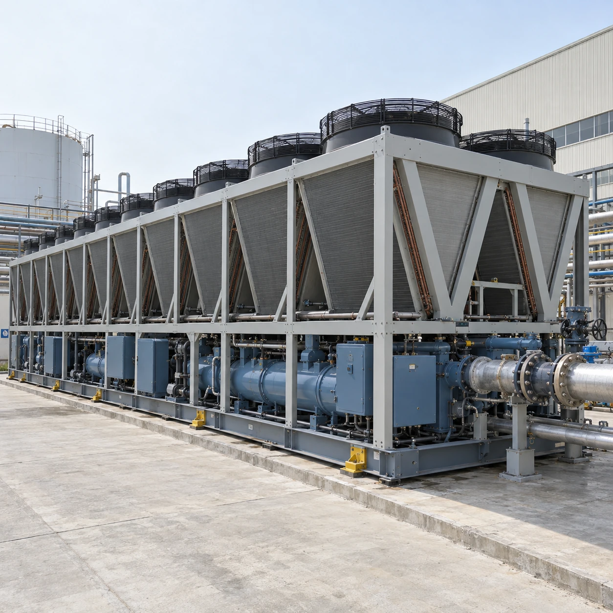
Air-Cooled Chillers
400 ton air cooled chiller
| Brand | shengtongJH |
|---|---|
| Nominal duty | 400 US RT = 1,406.74 kW thermal |
| Equipment options | Large screw unit or coordinated smaller-unit plant |
| Calculated water flow at 5 K rise | 241.96 m³/h for water |
| Single-unit envelope options, L × W × H (mm) | Approximately 12,700–13,900 × 2,250 × 2,520; alternative architectures differ |
| Hydraulic package | Separate pumps, headers, isolation, strainers and expansion/buffer equipment |
| Electrical supply | Industrial three-phase configuration; feed arrangement by selected unit |
| Capacity control | Multiple compressor/circuit operation or appropriate screw capacity control |
| Mounting requirements | Selected-unit support reactions, operating mass and lifting information |
| Plant control | Duty sequencing, external enable, alarm and monitoring interfaces |
Single-unit size classes are not multi-unit layouts. Cooling capacity is thermal output; transformer and feeder sizing requires selected electrical data.
Plant arrangement, electrical interfaces, water-side equipment and delivery configuration can be customized for your industrial site.
A 400 ton air cooled chiller introduces substantial thermal and infrastructure demands. Early coordination of power, foundations, delivery and condenser airflow prevents the equipment selection from becoming a late construction problem.
Resolve the electrical demand early
The thermal capacity is not the electrical input. Obtain operating power, maximum current, starting characteristics and the selected feed arrangement. Coordinate these with the site's transformer and distribution design before finalising the plant room or utility yard.
For multiple units, define the restart sequence after a power interruption. Simultaneous requests for cooling should not automatically cause every compressor and pump to start together.
Check the entire delivery path
Assess road access, turning space, shipping height, crane position and the available lifting radius. The completed operating arrangement may differ from the shipping configuration. Agree transport sections and site assembly requirements before construction closes off access.
Foundations and pipework must work together
Use the selected equipment's operating mass and support reactions for structural design. Account for fluid, accessories and the intended isolation arrangement. Pipework must be supported so its weight and thermal movement do not load the machine's connections beyond their limits.
Leave access for evaporator service and major component replacement. A layout that permits installation but prevents later removal creates an avoidable maintenance constraint.
Do not confine the condenser banks
Large equipment needs a large volume of intake air. Enclosing it with high walls or closely packing several units can cause hot-air recirculation. Review the actual geometry and wind conditions with the selected arrangement, including any acoustic screening.
A low-noise mode can change fan operation and available duty. Assess its performance at the time and condition when the noise limit applies instead of assuming full daytime output remains available.
Define the commissioning boundary
Agree responsibility for flushing, water treatment, electrical checks, controller integration and first operation. Record performance at the agreed available site conditions without presenting a partial-load site observation as proof of every rated condition. Where uninterrupted cooling is required, test the intended changeover and load-shedding sequence.
Plant arrangement, electrical interfaces, water-side equipment and delivery configuration can be customized for your industrial site.