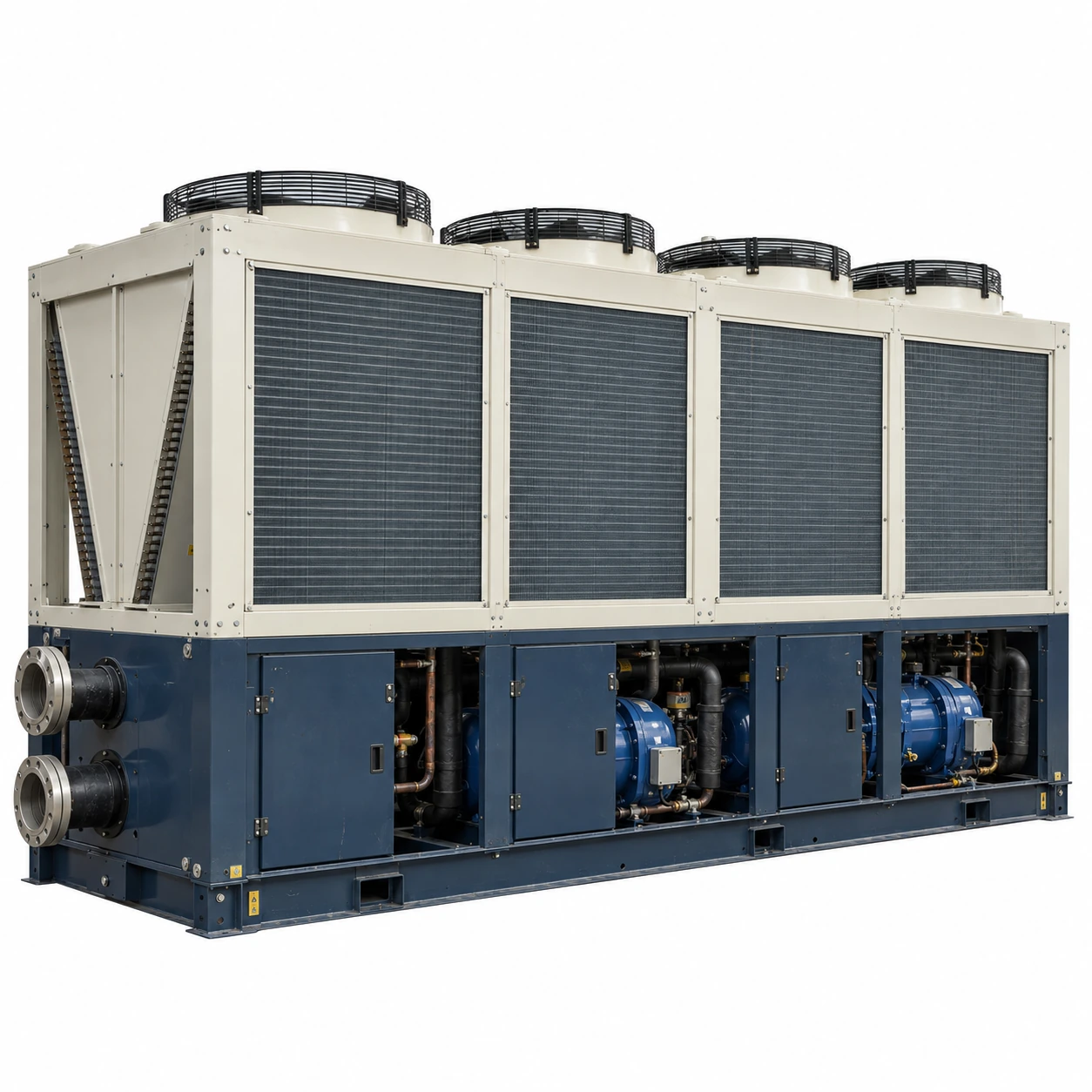
Air-Cooled Chillers
30 ton air cooled chiller
| Brand | shengtongJH |
|---|---|
| Nominal thermal duty | 30 US RT = 105.51 kW |
| Compressor configurations | Multiple scroll compressors or a suitable screw package |
| Calculated water flow at 5 K rise | 18.15 m³/h |
| Fluid circuit | Treated-water loop; isolated secondary process circuit where needed |
| Pump and tank | Integral or external arrangement according to pressure and useful storage volume |
| Envelope options, L × W × H (mm) | Approximately 2,500–3,600 × 1,200–1,800 × 1,800–2,300 |
| Electrical supply | Industrial three-phase configuration matched to site voltage and frequency |
| Condenser | Air-cooled finned coil with accessible cleaning surfaces |
| Controls | Flow proving, staged temperature control and external alarm/enable options |
Capacity must be checked at the required leaving-fluid and ambient temperatures. The selected unit determines input power, evaporator limits and final dimensions.
Fluid isolation, pumping, enclosure protection and control interfaces can be customized for your production line.
A 30 ton air cooled chiller can support a production line with several heat sources. A reliable configuration considers fluid quality, access for maintenance and the relationship between process-side heat transfer and refrigeration capacity.
Do not send every process fluid through the evaporator
Cooling circuits serving extrusion tools, oil coolers or process baths may contain different contaminants and additives. Sending an unsuitable fluid through a compact evaporator can cause blockage, corrosion or loss of heat transfer. Select the wetted materials from the real fluid chemistry.
A secondary heat exchanger can protect the chiller from a difficult process circuit. Its size and temperature approach must be included in the duty calculation, because the chiller may need to supply colder water to achieve the required process temperature.
Distinguish fouling from insufficient capacity
If the coolant leaves the chiller at the target temperature but the process remains hot, investigate flow and heat transfer at the load. Fouled channels, trapped air and an undersized exchanger can prevent useful cooling. A larger chiller does not automatically correct those restrictions.
Keep the condenser breathing
Production dust and airborne fibres can accumulate on fins. Arrange access for the cleaning method specified for the chosen coil, and avoid placing the unit directly in a dirty exhaust stream. A protected location should still leave the intake and discharge air paths open.
Organize service without unnecessary shutdowns
Use isolation around maintainable water-side components and provide drains where fluid must be removed. A pump or strainer placed behind permanent pipework can turn routine service into a prolonged interruption. The access layout should be reviewed before the equipment is ordered.
Where the line runs continuously, decide whether partial capacity during service is acceptable. Multiple refrigeration circuits can reduce some outage exposure, but shared electrical or hydraulic components still need attention.
Purchase against an operating duty
Specify the required cooling output at the selected fluid temperature and actual summer intake air. Include fluid composition, pressure limits and required flow. This allows shengtongJH to coordinate the refrigeration and water-side package around a production requirement rather than a cabinet size.
Fluid isolation, pumping, enclosure protection and control interfaces can be customized for your production line.