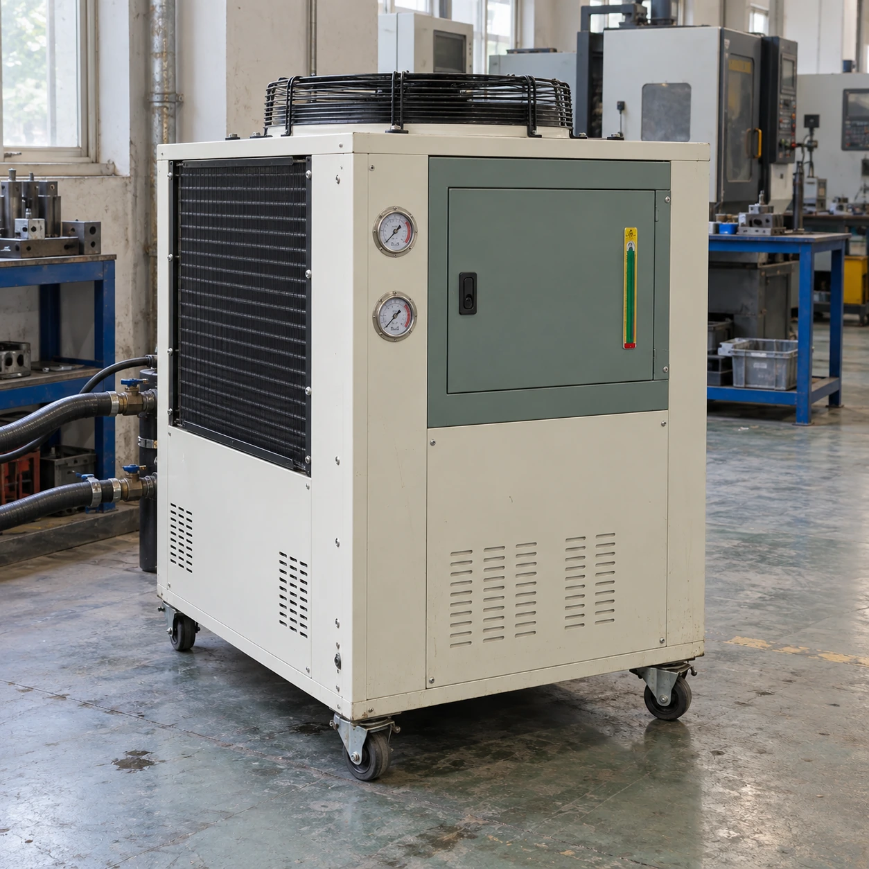
Air-Cooled Chillers
3 ton air cooled chiller
| Brand | shengtongJH |
|---|---|
| Nominal thermal duty | 3 US RT = 10.55 kW |
| Refrigeration package | Compact air-cooled compressor/condenser assembly |
| Calculated water flow at 5 K rise | 1.81 m³/h |
| Hydraulic options | Integrated reservoir/pump; separate secondary loop where required |
| Temperature selection | Positive-temperature water cooling selected from the process requirement |
| Envelope options, L × W × H (mm) | Approximately 1,000–1,200 × 600–800 × 1,100–1,400 |
| Supply | Three-phase industrial package; destination-specific alternatives by selection |
| Mobility | Fixed installation or castor-mounted cabinet |
| Operating protection | Flow and temperature interlocks, compressor protection and alarm output options |
A water chiller does not directly cool every process fluid. Confirm any intermediate heat exchanger, actual duty, electrical demand and final dimensions.
Water-side equipment, process separation and control connections can be customized to your production cell.
A 3 ton air cooled chiller is a practical size for a dedicated production cell when a shared factory loop is unavailable or unsuitable. It can supply a compatible water-side heat exchanger or tool circuit without mixing unrelated process fluids.
Keep the process fluid where it belongs
A hydraulic machine may need oil cooling, while a nearby tool needs water cooling. An air-cooled water chiller can support an appropriate oil-to-water heat exchanger, but oil should not simply be circulated through an evaporator designed for water.
The intermediate exchanger must transfer the required heat at the available temperature difference. Its resistance, fouling tendency and cleaning access are part of the cooling solution rather than accessories to select after the chiller arrives.
Measure the load during useful production
Machine electrical power includes energy that may leave through motion, ventilation or other cooling paths. It is not automatically the water-side heat load. Where conditions permit, measured coolant flow and supply/return temperatures provide a more direct basis for estimating the heat being removed.
Include the hottest sustained operating mode and any short production peak. Avoid adding an arbitrary large margin that leaves the chiller cycling at normal load.
Local heat and noise
A cabinet beside the machine keeps piping short but warms the work area. Ensure intake air remains within the selected unit's conditions throughout the shift. Place the unit so fan discharge does not immediately return to its own coil.
Service without moving the whole installation
Keep the strainer, pump, reservoir and electrical isolator accessible. Flexible connections should not carry the cabinet's weight or pull on fittings. Provide a controlled route for drainage during tool changes or maintenance.
Use simple operating records
Supply and return temperatures, fluid level and flow under a known production cycle form a useful baseline. A gradual change may point to a dirty exchanger or condenser; a sudden change after a hose replacement may point to a restriction or air in the circuit. This helps the operator investigate the cause instead of repeatedly lowering the setpoint.
Water-side equipment, process separation and control connections can be customized to your production cell.