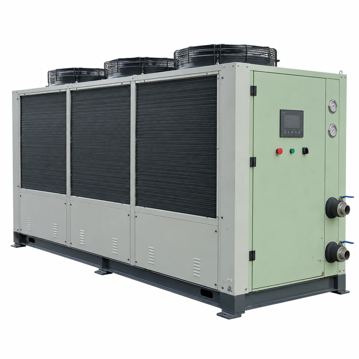
Air-Cooled Chillers
20 ton air cooled chiller
| Brand | shengtongJH |
|---|---|
| Nominal cooling capacity | 20 US RT = 70.34 kW thermal |
| Compressor options | Scroll package with one or more refrigeration circuits |
| Calculated water flow, 5 K rise | 12.10 m³/h |
| Hydraulic selection | Tank/pump package or separate distribution skid |
| Water temperature | Process-specific duty; common supply selection between 7°C and 15°C |
| Envelope options, L × W × H (mm) | Approximately 2,200–2,800 × 1,000–1,500 × 1,700–2,400 |
| Power supply | 380–415 V three-phase; frequency selected for the destination |
| Process connections | Branch manifold, isolation and balancing options |
| Supervision | Flow protection, temperature alarms and remote enable options |
The unit must be selected for actual water and air conditions. Flow, final electrical load and cabinet dimensions are confirmed as a matched package.
Branch distribution, pump pressure, storage and control functions can be customized for your production cell.
A 20 ton air cooled chiller can consolidate cooling for a small production cell. Sharing equipment reduces duplicated local units, but the common loop must still deliver the right temperature and flow to each machine.
One loop needs a compatible temperature
Before combining several machines, check whether they can use the same coolant temperature and fluid. Supplying all of them at the coldest required temperature may introduce condensation or unnecessary refrigeration work. Separate secondary circuits can give individual control where requirements differ.
A common pump does not guarantee equal flow
Water favours the branch with the least resistance. Long hoses, small internal passages and fouled tool circuits may receive less than expected. Provide balancing and a practical method of checking each branch rather than relying only on total flow at the chiller.
What happens when one machine stops?
If its valve closes, the common loop's flow and pressure change. The remaining machines must stay within their acceptable pressure range, and the evaporator must retain adequate circulation. Select a bypass or separate primary loop where needed; do not simply lock every valve open without considering process control.
The minimum active refrigeration step also matters when only one small machine remains in service. Useful buffer volume and suitable compressor control help prevent rapid temperature swings and repeated starts.
Keep a local fault from stopping the whole cell
Give each process branch accessible isolation and a clear identification. A leaking hose or dirty local strainer should be serviceable without draining every connected machine. For a load that cannot tolerate an interruption, consider a dedicated backup path rather than assuming the shared unit provides redundancy.
Specify the distribution alongside the chiller
Provide a list of machine flow requirements, temperature limits, connection sizes and operating schedules. Include the approximate pipe route and elevation differences where an open system is involved. The selected pump must satisfy the actual circuit, not an assumed distance-based rule.
At handover, record branch settings and the expected temperatures during normal production. These become a useful baseline when a later process change is mistaken for a refrigeration fault.
Branch distribution, pump pressure, storage and control functions can be customized for your production cell.