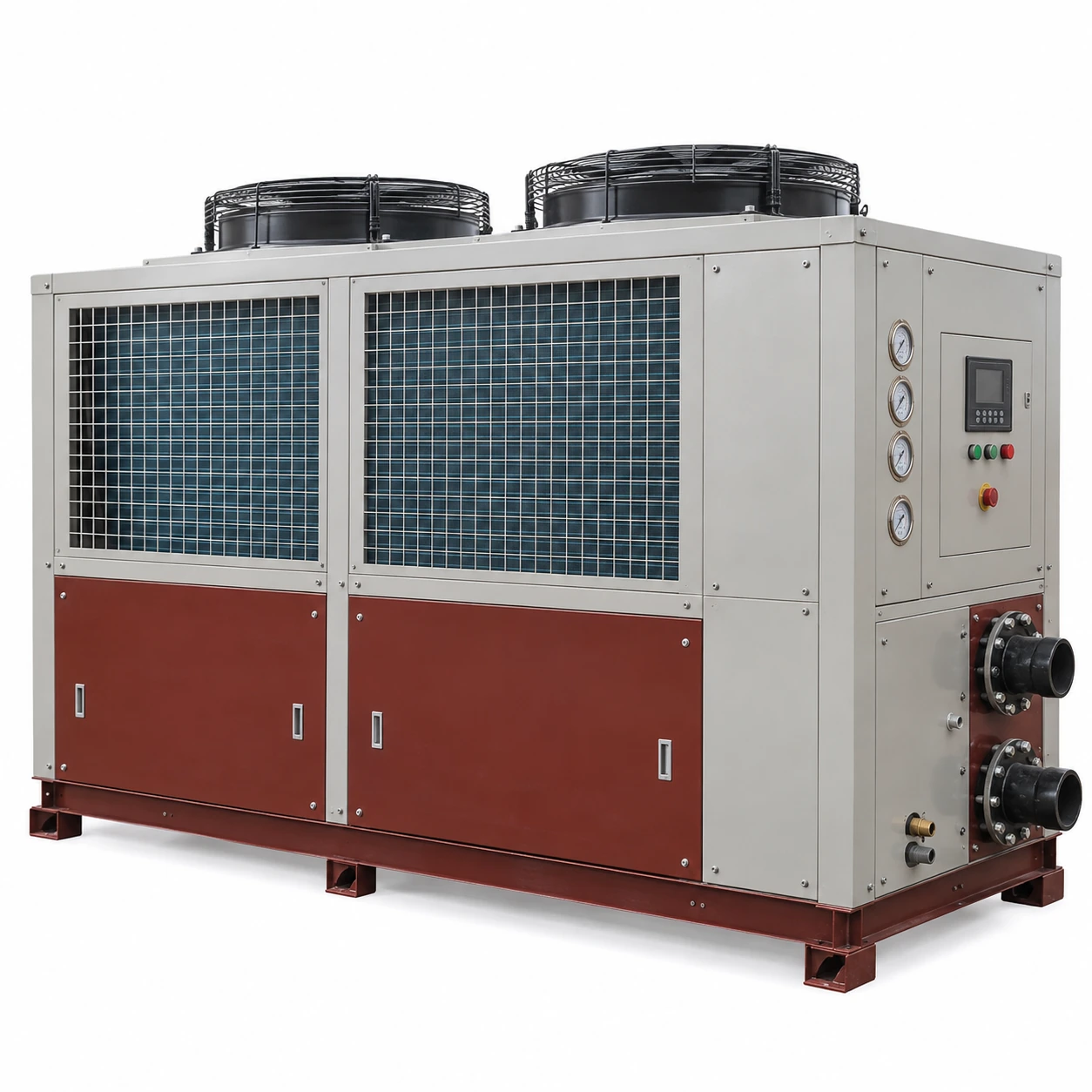
Air-Cooled Chillers
15 ton air cooled chiller
| Brand | shengtongJH |
|---|---|
| Nominal thermal capacity | 15 US RT = 52.75 kW |
| Refrigeration configuration | Scroll compressor package with air-cooled condenser |
| Calculated water flow, 5 K rise | 9.07 m³/h |
| Water-side options | Integral reservoir and pump; separate buffer or secondary circuit |
| Operating temperatures | Supply/return temperatures selected for the process and summer ambient |
| Envelope options, L × W × H (mm) | Approximately 1,700–2,300 × 900–1,200 × 1,500–2,000 |
| Electrical supply | 380–415 V three-phase, or destination-specific configuration |
| Controls | Temperature controller, compressor staging where fitted, flow interlock and remote alarm |
| Installation format | Indoor package with adequate ventilation or purpose-selected outdoor unit |
Duty is selected at stated operating conditions. Calculated flow is not a pump guarantee; final dimensions and input power follow the selected package.
Reservoir volume, circulation, controls and installation format can be customized for your production cycle.
A 15 ton air cooled chiller can support cyclic production where heat arrives in bursts. The key question is how quickly the process must recover between cycles, not simply how much heat is released over an entire shift.
Separate a short peak from a sustained load
A batch may release heat rapidly and then remain idle. A larger active water volume can absorb some of that short peak while refrigeration restores the water temperature before the next cycle. If the next batch arrives too soon, the water temperature can drift upward over successive cycles.
Record the energy removed per batch, permitted pull-down time and spacing between batches. For continuous work, use the sustained heat rate. A buffer should not be treated as unlimited extra capacity.
Put the temperature sensor where it answers the right question
A sensor at the chiller outlet describes the supplied coolant; it does not necessarily describe the temperature inside a jacket or mould. Poor circulation or heat-exchanger fouling can separate those conditions. Process-side monitoring helps determine whether a delay is caused by the refrigeration unit or by heat transfer at the load.
Keep return conditions within the unit's limits
A hot batch can produce a high initial return-water temperature. Check that the selected evaporator and compressor can accept it. A mixing arrangement or separate heat exchanger may be needed rather than sending the hottest process fluid directly into the chiller.
More flow is not always the cure
Increasing flow may improve a poorly supplied branch, but it also raises pumping demand and can exceed equipment pressure or flow limits. Check the actual flow, temperature difference and heat-exchanger condition before changing the pump. Select the pump from the full circuit resistance.
A configuration that operators can use
Provide a readable temperature indication, clear alarm status and accessible water-level checks where an open reservoir is used. Place drains and strainers where service does not flood the production area. For equipment moved between work cells, confirm the electrical connection, hose pressure rating and room heat-rejection provision each time it is relocated.
The final selection should state the required recovery time and permissible coolant temperature variation, making the quotation meaningful to both purchasing and production staff.
Reservoir volume, circulation, controls and installation format can be customized for your production cycle.