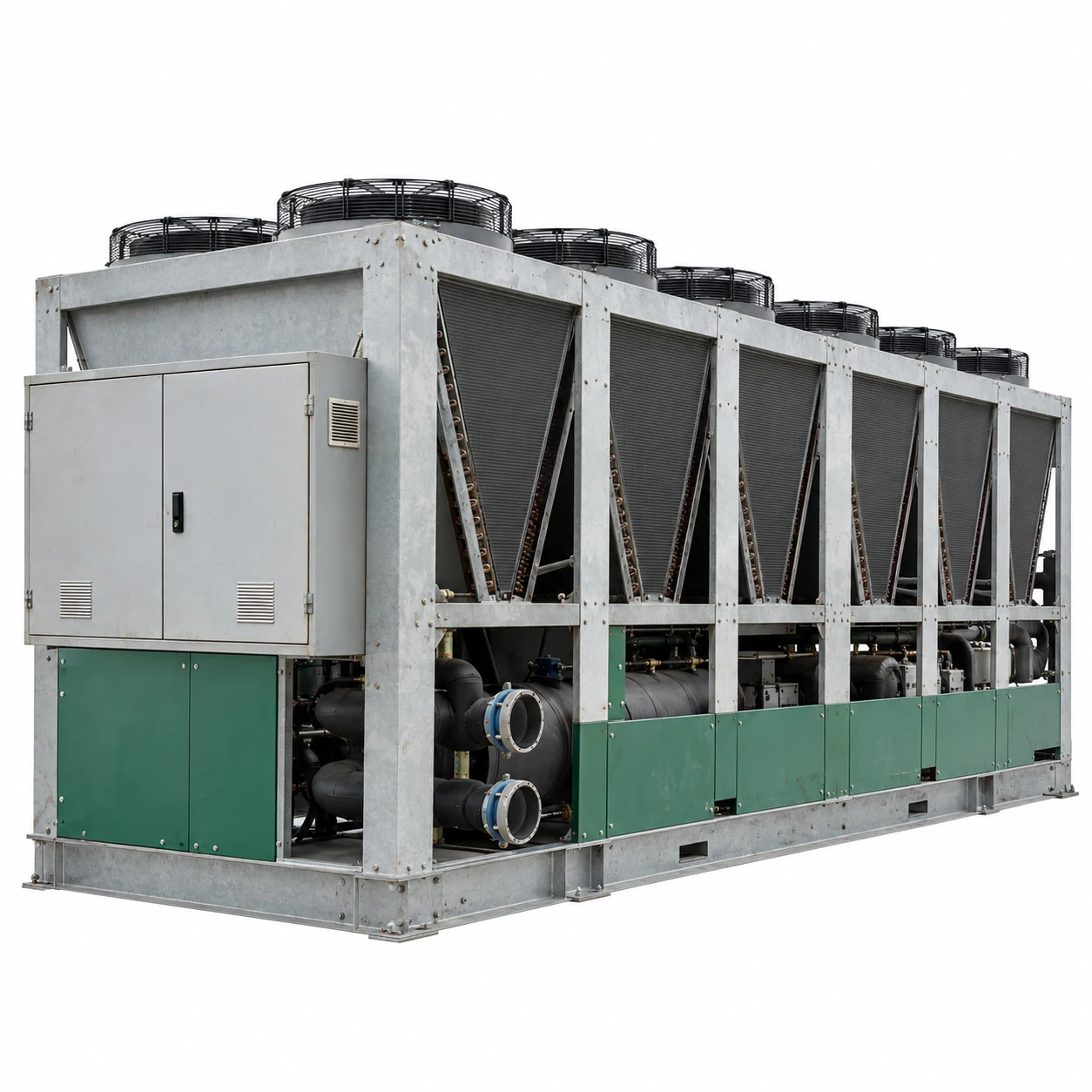
Air-Cooled Chillers
100 ton air cooled chiller
| Brand | shengtongJH |
|---|---|
| Nominal cooling duty | 100 US RT = 351.69 kW thermal |
| Compressor options | Multiple scroll compressors or screw compressor package |
| Calculated water flow at 5 K rise | 60.49 m³/h for water |
| Temperature basis | Process-specific supply/return water; capacity selected at the design ambient |
| Envelope options, L × W × H (mm) | Approximately 4,500–6,500 × 2,000–2,500 × 2,100–2,600 |
| Hydraulic package | External pump/tank equipment or compatible integrated module |
| Electrical configuration | 380–415 V three-phase; frequency and electrical demand matched to the selected package |
| Control options | Circuit staging, remote start/stop, alarm contacts and plant communication |
| Site options | Coil corrosion protection, vibration isolation and compatible low-ambient equipment |
Published capacity classes do not establish output at every water temperature. Final dimensions, electrical load and fluid limits are specified with the chosen unit.
Cooling circuits, hydraulic interfaces and site protection can be customized for your factory layout and operating conditions.
A 100 ton air cooled chiller can supply a shared factory cooling loop where several production areas need a common water temperature. Its value depends on delivering stable cooling to the most demanding branch while adjusting to changes elsewhere in the plant.
Use simultaneous load, not the sum of every possible maximum
A central cooling loop may serve presses, heat exchangers and production air handlers with different schedules. Adding all nameplate maxima can oversize the plant; assuming that no loads overlap can undersize it. A load schedule tied to real production modes gives a more useful selection basis.
Identify the branch with the strictest temperature requirement. Cooling all users to that temperature may be wasteful if most can operate warmer. A secondary heat exchanger or a separate small chiller can sometimes isolate the demanding process and let the main plant operate at a more suitable supply temperature.
Keep distribution losses visible
Long pipe runs, dirty strainers and poorly balanced branches can make the remote machine appear undercooled. Check the temperature and flow at that machine, not only at the chiller outlet. Insulate cold pipework and protect the vapour barrier to control heat gain and surface condensation.
Select the lowest useful operating step
At reduced production, a large minimum compressor step can cause frequent cycling. Compare the minimum stable capacity of the proposed package with the lowest sustained process load. Suitable staging, variable capacity and adequate active water volume address different parts of this problem.
Do not let the installation create a hotter climate
Closely spaced units, high parapets and restrictive screening can return hot discharge air to the coils. The machine then operates at a higher intake temperature than the weather report suggests. Evaluate the actual yard or roof arrangement, including prevailing wind and neighbouring heat sources.
Electrical and maintenance access must remain practical after screens and pipework are fitted. Agree the service route and lifting provision before the plant is surrounded by permanent construction.
Request a comparable selection
Ask for cooling output, input power and water pressure drop at the same ambient, fluid and temperature conditions from each proposed configuration. This prevents a nominal rating at favourable conditions from being compared with a genuine summer-duty selection. Compare both full-load and representative reduced-load operation.
Cooling circuits, hydraulic interfaces and site protection can be customized for your factory layout and operating conditions.