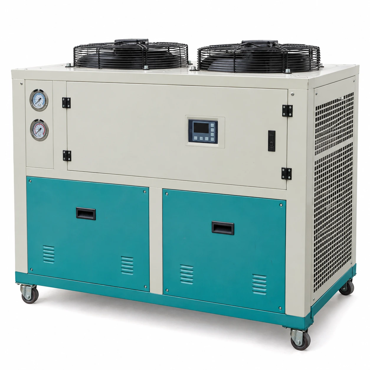
Air-Cooled Chillers
10 ton air cooled chiller
| Brand | shengtongJH |
|---|---|
| Nominal cooling duty | 10 US RT = 35.17 kW thermal |
| Selection condition | Specify entering/leaving water and condenser inlet-air temperature; request a duty selection at the site's summer condition |
| Compressor / condenser | Scroll configuration; fan-assisted air-cooled condenser |
| Calculated water flow | 6.05 m³/h for water with a 5 K temperature rise |
| Water equipment | Integral insulated tank and process pump, or external hydraulic package |
| Envelope options, L × W × H (mm) | Approximately 1,300 × 800 × 1,400 to 2,000 × 1,000 × 1,800, depending on tank and condenser arrangement |
| Electrical supply | 380–415 V, three-phase, 50 Hz; destination-specific alternatives by configuration |
| Working fluid | Treated water; compatible inhibited glycol where required |
| Protection | Flow interlock, water-temperature protection, compressor overload and refrigeration pressure protection |
The flow is a heat-balance calculation, not a supplied pump rating. Confirm unit output, input power and final envelope on the selected configuration.
The tank, pump, water connections and controls can be customized to suit your production equipment and installation space.
A 10 ton air cooled chiller suits a defined medium-size process load or a small group of production tools. Selection should account for their simultaneous heat release and the water temperature they require, rather than simply adding equipment nameplate power.
Allow for real production overlap
Two tools rarely release heat in exactly the same way throughout a shift. One may cool continuously while another creates a short peak after a cycle. Record those patterns before deciding whether one shared unit can serve both. A tank can absorb a short mismatch; it cannot make up a continuous shortage of refrigeration.
Where product quality depends on steady mould or jacket temperature, compare the required cooling-water stability with the selected control arrangement. Do not confuse the display resolution with guaranteed temperature stability at the process.
Keep one branch from starving another
A short, low-resistance hose can take most of a common pump's flow while a distant tool receives too little. Balance the branches and provide a way to verify their flow. If the tools need different temperatures or fluids, separate secondary circuits may be more appropriate than a single shared supply.
The tank and pump are working components
An integral tank is convenient for a compact installation, but useful volume, fluid compatibility and access for cleaning matter more than tank presence. The pump should be selected against pipe losses, fittings, strainers and the process heat exchanger. An optional larger pump must also remain within the allowable pressure of hoses and tools.
Position the unit for a full shift of operation
Placing a chiller beside a production machine keeps water lines short, but its rejected heat enters the same space. In a poorly ventilated workshop the air temperature can climb through the day, reducing cooling just when demand is high. An outdoor-rated package or a suitable remote heat-rejection arrangement may solve the heat problem more effectively than increasing nominal capacity.
For the quotation, include the normal and maximum return-water temperatures, required branch flows, operating hours and the summer air temperature at the intended coil intake. These details determine whether the selected unit will meet the actual duty.
The tank, pump, water connections and controls can be customized to suit your production equipment and installation space.