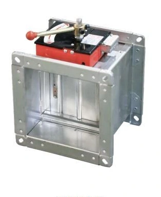
Fire & Smoke Control Dampers
Smoke Exhaust Fire Damper
| Specification | Smoke-exhaust configuration |
|---|---|
| System role | Smoke-extraction route with protective closure function |
| Body form | Rectangular flanged casing |
| Blade arrangement | Multi-blade closure |
| Dimensions | Selected to the duct and supported assembly |
| Control sequence | Coordinated with extraction fan and fire controls |
| Thermal response | Selected to the required smoke-exhaust assembly |
Dimensions and configurations can be customized for your application.
A smoke exhaust fire damper forms part of a smoke-extraction route and its specified protective closure sequence. Its normal position, commanded operation and thermal response must match the smoke-control design.
Keep extraction and protective closure coordinated
Smoke extraction requires a defined route from the selected area to the discharge system. A smoke exhaust fire damper contributes to that route while providing a specified protective closing function. It must therefore be selected from the intended system sequence, rather than treated as a general ventilation damper with a different label.
The required behaviour can include an open extraction path during a smoke-control mode and a separate closure response under defined conditions. Establish these states with the project design. Closing every damper immediately on any alarm would not necessarily support the intended extraction strategy.
Write down the cause and effect
Identify the normal position, which signal initiates the smoke mode, what confirms the damper position and how the extraction fan responds. Include the thermal closure function and reset procedure where they belong to the selected assembly.
This sequence should be checked across the connected equipment. A fan command alone does not establish an open extraction path, and an open-position signal alone does not prove that the required airflow has been achieved.
Know which product has been selected
Smoke exhaust fire dampers, smoke-control dampers and ordinary fire dampers can serve different roles. The evidence and installation instructions must apply to the actual selected assembly. A familiar translated product name is not sufficient to establish approval for a destination project's requirements.
Fit the damper without restricting its movement
Coordinate the casing with the duct connection, supporting structure and available service space. Keep installation loads from twisting the body. The blades and linkage need unobstructed movement after the duct has been insulated and surrounding work is complete.
Locate controls and inspection openings where the mechanism can be reached. A damper hidden behind fixed ceilings or process services can become difficult to check, even though the visible duct installation appears complete.
Commission the route as a system
Position
Check the commanded and physical states against the intended sequence.
Interfaces
Confirm the fan, alarm and feedback relationships without substituting a local hand movement for a system functional check.
Maintenance
Retain access and the specified inspection procedure so the operating sequence remains serviceable after handover.
Dimensions, connections and controls can be customized within the supported assembly and project smoke-control requirements. Discuss the extraction and closure sequence.