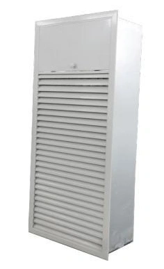
Fire & Smoke Control Dampers
Multi-Blade Smoke Exhaust Damper
| Specification | Multi-blade smoke-exhaust assembly |
|---|---|
| Function | Controlled opening for smoke extraction |
| Form | Rectangular multi-blade assembly |
| Installation | Coordinated with the smoke-extract duct or shaft opening |
| Dimensions | Selected to the required opening and supported assembly |
| Operation | Selected to the smoke-control sequence |
| Access | Service access to the mechanism and blades |
Dimensions and configurations can be customized for your application.
A multi-blade smoke exhaust damper controls the opening into a designated smoke-extraction route. The blade assembly and operating mechanism need to follow the extraction strategy for the area being served.
Open the right path at the right time
A smoke-extraction system needs to connect the affected area to the intended exhaust route. A multi-blade damper controls that opening. Its role is not simply to shut whenever smoke is detected; the required response depends on which area is being extracted and how the wider system is arranged.
Define the normal and smoke-mode positions for each opening. This prevents a local device from being connected with a generic control sequence that conflicts with the planned smoke route. The selected assembly and supporting evidence should match the project requirements for the destination building.
Size the opening for useful extraction
The visible face area is not the same as the free passage available when the blades are open. The frame, blade geometry and actual opening position affect resistance. Select the assembly using the required exhaust duty and the pressure available through the whole route.
Coordinate the adjacent duct or shaft so that the damper does not face an immediate obstruction. A large visible grille cannot compensate for a restricted connection behind it. Include the supporting frame and any decorative interface in the installation drawing.
Make the controls unambiguous
Command
Identify the signal that calls for operation and how local controls interact with the central smoke-control system.
Confirmation
Where position feedback is required, coordinate the signal with actual blade travel rather than only the actuator command.
Reset
Provide a clear return-to-normal procedure after a functional check or event. Access to the mechanism should remain available after finishing work.
Keep the opening clear in everyday use
Stored materials, furniture and later fit-out work can obstruct an exhaust opening even when its mechanism still operates. Locate the face where the required air path can be maintained, and keep its purpose clear during building operation.
Inspect the blades and linkage for interference after installation. Do not apply finishes or fixings that bridge moving components. The functional check should include the connected control sequence, not only a visual look at the closed face.
Coordinate the complete assembly
Provide the required opening, wall or shaft interface, extraction duty and operating sequence for selection. Damper dimensions, face arrangement and controls can be customized within the supported assembly scope and project requirements. Discuss the smoke-exhaust opening.