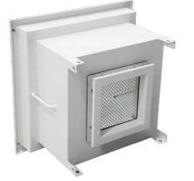
Side gel-seal HEPA terminal housing
Fan Filter Units & Air Terminals
Side Gel-Seal HEPA Terminal Housing
| Specification | GK-5A | GK-10A | GK-15A | GK-20A | GK-22A | GK-30A |
|---|---|---|---|---|---|---|
| Duct entry | Top | Top | Top | Side | Side | Side |
| Rated airflow (m³/h) | 500 | 1000 | 1500 | 500 | 1000 | 1500 |
| Housing dimensions (mm) | 490 × 490 × 280 | 640 × 640 × 280 | 720 × 720 × 280 | 490 × 490 × 380 | 640 × 640 × 380 | 720 × 720 × 380 |
| Filter dimensions (mm) | 400 × 400 × 90 | 550 × 550 × 90 | 630 × 630 × 90 | 400 × 400 × 90 | 550 × 550 × 90 | 630 × 630 × 90 |
| Diffuser dimensions (mm) | 555 × 555 × 15 | 705 × 705 × 15 | 785 × 785 × 15 | 555 × 555 × 15 | 705 × 705 × 15 | 785 × 785 × 15 |
| Seal arrangement | Side gel seal | |||||
| Housing material | Powder-coated cold-rolled steel | |||||
Dimensions and configurations can be customized for your application.
A side gel-seal terminal combines final filtration with a matched gel-channel and sealing-edge interface. The housing and replacement filter must share the same seal geometry so that supply air passes through the media rather than around its perimeter.
A seal designed into the filter interface
A gel seal uses a sealing edge engaging with a compatible gel channel around the filter perimeter. Its purpose is to prevent bypass at the frame. The relationship between these parts matters more than whether a replacement element simply fits inside the box.
For this side-seal arrangement, confirm the channel location, edge orientation and engagement with the selected filter. Side gel seal describes the filter interface; it does not dictate the direction of the supply duct. Top and lateral duct connections can serve different ceiling layouts.
Avoid the almost-compatible replacement
A filter with the correct overall dimensions can still have the wrong seal position or frame profile. For an existing installation, identify the installed interface before ordering. The drawing should show how the filter enters, where it is supported and how the sealing edge engages without damaging the channel.
Check the condition of the gel and mating edge during replacement. Debris, a bent edge or damaged frame can create a local bypass path. Keep protective packaging in place until handling is required and support the element by its frame rather than by the media surface.
Three details that make installation easier
Independent support
Support the housing so that duct loads do not twist it. A stable box gives the filter a consistent seating geometry and makes retaining components easier to operate.
Access to the interface
Leave room to remove the diffuser and reach the retention points. Service clearance should be coordinated with lights, equipment and other ceiling components.
Test access
Where installed integrity testing is required, coordinate upstream aerosol introduction and sampling access with the selected housing. The test arrangement must allow a meaningful check of the installed assembly.
Sealing and airflow have separate jobs
The gel interface controls perimeter leakage. The filter media captures particles, while the plenum and diffuser influence how supply air reaches the room. A good perimeter seal cannot compensate for an obstructed diffuser or an unbalanced supply system.
Commission the outlet within the complete room airflow arrangement. After filter replacement, restore the operating condition and complete the checks required by the process rather than assuming that an undamaged-looking element is enough.
Keep maintenance information with the terminal
Record the filter dimensions, seal arrangement and service direction so future replacements remain compatible. Housing dimensions, duct entry and access details can be customized to the application. Discuss the sealing interface and ceiling layout.