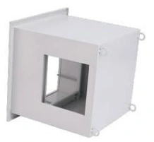
Mini-pleat HEPA terminal housing
Fan Filter Units & Air Terminals
Mini-Pleat HEPA Terminal Housing
| Specification | GK-5A | GK-10A | GK-15A | GK-II 5A | GK-II 10A | GK-II 15A |
|---|---|---|---|---|---|---|
| Duct entry | Top | Top | Top | Side | Side | Side |
| Rated airflow (m³/h) | 500 | 1000 | 1500 | 500 | 1000 | 1500 |
| Housing dimensions (mm) | 360 × 360 × 310 | 530 × 530 × 310 | 670 × 670 × 310 | 360 × 360 × 375 | 530 × 530 × 375 | 670 × 670 × 375 |
| Filter dimensions (mm) | 320 × 320 × 90 | 484 × 484 × 90 | 630 × 630 × 90 | 320 × 320 × 90 | 484 × 484 × 90 | 630 × 630 × 90 |
| Diffuser dimensions (mm) | 430 × 430 × 15 | 600 × 600 × 15 | 740 × 740 × 15 | 430 × 430 × 15 | 600 × 600 × 15 | 740 × 740 × 15 |
| Housing material | Powder-coated cold-rolled steel | |||||
| Filter format | Mini-pleat | |||||
Dimensions and configurations can be customized for your application.
Combine a compact final filter, terminal plenum and room-side diffuser in a coordinated supply outlet. Top and side duct connections allow the housing to be matched to the ceiling void and supply-air route.
Final filtration where air enters the room
The terminal housing puts the final filter close to the room boundary. Supply air enters a plenum, passes through the filter and leaves through the diffuser. Coordinating these components helps avoid a common installation problem: a filter, box and face panel that are individually suitable but do not fit or seal properly together.
A mini-pleat element packs filtration media into a relatively shallow frame. This can help where ceiling space is constrained, but the complete installation still needs room for the duct connection, suspension and filter removal. The filter's shallow profile should not be mistaken for the depth of the entire terminal.
Choose the duct route before fixing the ceiling
Top entry
A connection above the housing suits a supply branch approaching from overhead. Allow enough room for the connection and any bend so that the duct is not forced into a tight, distorted route.
Side entry
A lateral connection can suit a branch running across the ceiling void. Its approach should avoid nearby services and allow the plenum to distribute the incoming air across the filter.
Room interface
Coordinate the face opening, surrounding ceiling and support. The housing should sit square without depending on ductwork to hold it in position.
A clean filter still needs a sound perimeter
The frame seal prevents air from passing around the media. Keep the seating surface clean and undamaged, and use the retention arrangement intended for the selected element. Uneven clamping can distort the frame; extra force is not a substitute for a compatible filter and seat.
The diffuser distributes the filtered supply into the occupied area. Its role is different from filtration, and room performance also depends on outlet placement, return paths and obstructions. Adding a terminal by itself does not establish the cleanliness classification of the room.
Make balancing and changeout accessible
Provide access to the selected airflow-adjustment point and a practical route for removing the diffuser and filter. Check these operations against lighting, process equipment and ceiling obstructions before installation. A serviceable layout reduces the temptation to disturb adjacent components during maintenance.
At commissioning, verify the installed flow and perform the filtration checks required by the application. Retain the filter identity and installation information for future replacement. Duct entry, housing dimensions and diffuser arrangement can be customized for the room layout. Plan the terminal installation.