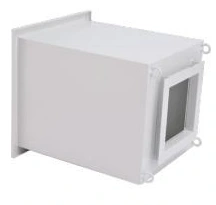
Deep-pleat HEPA terminal housing
Fan Filter Units & Air Terminals
Deep-Pleat HEPA Terminal Housing
| Specification | GK-5B | GK-10B | GK-15B | GK-II 5B | GK-II 10B | GK-II 15B |
|---|---|---|---|---|---|---|
| Duct entry | Top | Top | Top | Side | Side | Side |
| Rated airflow (m³/h) | 500 | 1000 | 1500 | 500 | 1000 | 1500 |
| Housing dimensions (mm) | 360 × 360 × 450 | 530 × 530 × 450 | 670 × 670 × 450 | 360 × 360 × 490 | 530 × 530 × 490 | 670 × 670 × 490 |
| Filter dimensions (mm) | 320 × 320 × 220 | 484 × 484 × 220 | 630 × 630 × 220 | 320 × 320 × 220 | 484 × 484 × 220 | 630 × 630 × 220 |
| Diffuser dimensions (mm) | 430 × 430 × 15 | 600 × 600 × 15 | 740 × 740 × 15 | 430 × 430 × 15 | 600 × 600 × 15 | 740 × 740 × 15 |
| Housing material | Powder-coated cold-rolled steel | |||||
| Filter format | Deep-pleat, separator type | |||||
Dimensions and configurations can be customized for your application.
A deep-pleat terminal housing accommodates a separator-style HEPA filter within a dedicated supply plenum. It provides a coordinated way to connect the duct, retain the filter and distribute the filtered air into the room.
Keep the housing compatible with the filter
A deep-pleat element uses separators to maintain the passages between pleated media. Its frame depth and retaining arrangement differ from a shallow mini-pleat element. Selecting the housing around the intended filter avoids improvised spacers, inadequate engagement and a diffuser that cannot close after installation.
This is particularly useful when replacing an existing terminal or maintaining a facility that already uses a defined filter format. Match the complete interface: outside frame, sealing face, depth, retaining method and removal direction. A matching face dimension alone does not establish interchangeability.
Check the service envelope, not only the box
A deeper assembly needs space above and below its installed position. Above the ceiling, coordinate suspension, supply connection and other services. Below it, allow a clear route for the element to be lowered and handled without touching the media or colliding with equipment.
Where the process layout restricts access, resolve the replacement method before the ceiling is closed. The most compact duct route may not be the most useful arrangement if it blocks the retaining hardware or makes later inspection difficult.
Top or side connection
Choose the connection that suits the actual supply branch. Keep bends and transitions orderly and avoid using the housing as a support for misaligned ductwork. Independent support helps the box retain its shape and protects the filter seat from installation stresses.
Control the air path through the assembly
Supply air should reach the filter through the plenum and leave through the intended room-side face. Gaps at the frame, damaged seals or poorly fitted panels create bypass routes. Inspect these interfaces during installation and whenever the element is changed.
Balance the terminal as part of the complete supply-and-return system. Increasing flow at one outlet can change distribution elsewhere; it is not a reliable way to solve every local cleanliness problem. Equipment positions, people and return-air access also influence the room's airflow.
Prepare for repeatable maintenance
Identify the element
Record the selected filter specification and seal arrangement so that the next replacement matches the installed housing.
Protect the seat
Remove debris and inspect the contact surface before fitting a new element. Address damage instead of hiding it with excessive clamping.
Check the result
Restore the required airflow and complete the installed filtration checks specified for the room after work is finished.
Housing, connection and diffuser details can be customized around the filter format and service space. Discuss the terminal and replacement requirements.