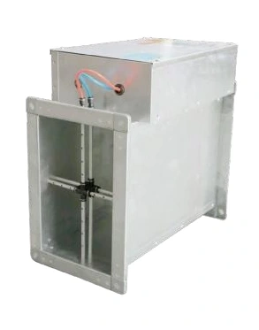
Air Volume Control Dampers
Variable Air Volume Terminal Unit
| Specification | Rectangular VAV terminal |
|---|---|
| Airflow function | Variable air volume control |
| Duct arrangement | Rectangular terminal casing |
| Control assembly | Airflow sensing, actuator and controller coordinated to the system |
| Connection | Flanged duct connection |
| Dimensions | Matched to the selected airflow duty and ductwork |
| Setpoints | Minimum and maximum airflow selected for the application |
Dimensions and configurations can be customized for your application.
A variable air volume terminal adjusts its damper to deliver a changing airflow demand. It provides a controllable branch element for systems where the required supply or extract volume varies with the operating condition.
Respond to a changing airflow demand
A room may need different ventilation volumes during production, reduced operation and recovery. A VAV terminal changes its damper position to serve that changing demand. In a measured-flow control arrangement, the controller compares the sensed airflow with the active setpoint and moves the actuator to reduce the difference.
This is different from simply commanding a motorized blade to a percentage open. A particular blade position cannot guarantee the same airflow when duct pressure changes. The sensing and control arrangement is what allows the terminal to respond to those changes within its operating range.
Give the sensor a usable flow condition
The location of the terminal affects measurement quality. Strongly uneven flow from a nearby bend, branch or abrupt transition can influence the pressure signal used to determine volume. Follow the selected terminal's installation requirements and reserve the necessary approach space before the duct route is finalized.
Keep sensing tubes accessible and protected from damage. The sensor arrangement should also suit the air stream: dust or deposits can interfere with small pressure passages. A terminal intended for relatively clean supply air should not automatically be selected for a contaminated process exhaust.
Set limits around the room's purpose
Minimum airflow
Reduced operation still needs to respect ventilation, process and pressure requirements. Select the lower limit from the application rather than reducing it only to save fan energy.
Maximum airflow
The upper limit must be achievable with the available duct pressure and compatible with downstream outlets. Excessive pressure can create noise even when the control target is met.
Room coordination
Where supply and extract both vary, coordinate their sequences with the intended pressure relationship. Independent changes can disturb the room even if each terminal reaches its own setpoint.
Commission the complete loop
Confirm the airflow direction, sensor connections, actuator travel and controller settings. Compare the indicated volume with an appropriate measurement under the selected operating conditions. Test the transitions between operating modes so that stable operation is demonstrated beyond a single setpoint.
Define the response to a failed signal or power loss and make controller access practical for future service. Terminal size, control interface and operating range can be customized around the room's ventilation sequence. Discuss the variable-airflow requirement.