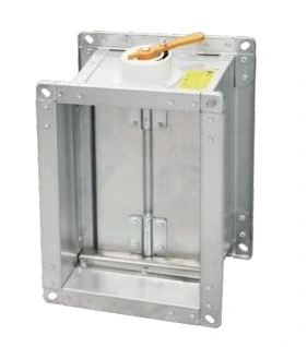
Handle-operated volume control damper
Air Volume Control Dampers
Manual Volume Control Dampers
| Specification | Handle | Worm gear | Lever | Underside adjustment | Slide gate |
|---|---|---|---|---|---|
| Operating method | Direct handle | Geared manual drive | Direct lever | Adjustment from below | Sliding plate |
| Pictured duct form | Rectangular | Circular | Circular | Rectangular | Rectangular |
| Application | Branch balancing | Branch balancing | Branch balancing | Accessible branch balancing | Adjustable branch restriction |
| Dimensions | Matched to ductwork | ||||
Dimensions and configurations can be customized for your application.
Manual volume control dampers provide a settable restriction for balancing ventilation branches. Different operating mechanisms make the adjustment accessible in different duct positions and service spaces.
Balance the branches without hiding the adjustment
Air naturally favours the easier path through a duct network. A manual balancing damper adds controlled resistance to a branch so that the required distribution can be established across the system. Once adjusted, its position is retained for normal operation.
The mechanism should be chosen around access, not only the duct shape. An inexpensive handle can become impractical if it ends up against a wall or above a closed ceiling with no access panel. The useful product is the one that can be adjusted, identified and checked after the building is finished.
Five ways to reach the setting
Handle or lever
A direct mechanism gives a straightforward adjustment where the side of the duct is accessible. Reserve enough clearance for its movement and the operator's hand.
Worm-gear drive
A geared mechanism allows deliberate incremental movement. It can suit an installation where controlled positioning is preferable to moving a blade directly with a short lever.
Underside adjustment
Adjustment from below can improve service access in a crowded ceiling void. Coordinate the operating point with an actual access opening in the finished ceiling.
Slide gate
A sliding plate changes the available passage in a different way from a rotating blade. Allow room for its travel and service access; its position should not be interpreted using a rotary-blade angle scale.
Set airflow with a measurement
A halfway handle position does not mean half the design volume. Flow depends on available pressure, blade position and the rest of the network. Balance the branch with a suitable airflow measurement and repeat the network checks as adjustments change the distribution.
Once the required duty is established, secure and record the setting. If the fan speed, filters, room outlets or connected branches change later, review the balance rather than assuming the old positions still deliver the same result.
Avoid unnecessary throttling noise
A heavily restricted damper may indicate excessive branch pressure or an unsuitable system arrangement. Where noise is a concern, review the fan duty and the location of the restriction instead of simply hiding the sound behind a grille.
Keep the installation serviceable
Fit the body squarely, support adjoining ducts and keep insulation clear of moving parts. Mark the operating point so maintenance personnel can find it without disturbing unrelated equipment. Duct size, operating mechanism and access arrangement can be customized to the installation. Discuss the balancing and access requirements.