Air Filters
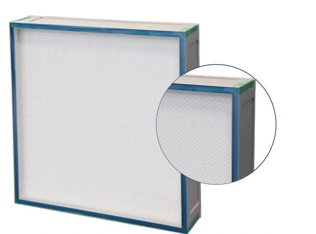
Top Gel Seal HEPA Filter
| Specification | 400 × 400 | 550 × 550 | 630 × 630 | 945 × 630 | 1260 × 630 |
|---|---|---|---|---|---|
| Series | JN-SGSHP | ||||
| Overall size (W × H × D, mm) | 400 × 400 × 95 | 550 × 550 × 95 | 630 × 630 × 95 | 945 × 630 × 95 | 1260 × 630 × 95 |
| Nominal airflow (m³/h) | 500 | 1000 | 1500 | 2000 | 3000 |
| Filter grade | H14 | ||||
| Frame / media | Aluminium alloy / microglass fibre | ||||
| Pack construction | Hot-melt spacing; polyurethane potting | ||||
| Face protection | Coated steel mesh | ||||
| Seal interface | Top gel channel | ||||
| Maximum operating temperature / humidity | 80°C / 80% RH | ||||
Dimensions and configurations can be customized for your application.
A top gel seal panel places the sealing interface on the upper frame edge. It is suited to a compatible housing that engages that channel, with the media pack below providing the final particulate-filtration stage.
Bring the upper seal into the housing design
The sealing channel is part of the frame geometry, not an interchangeable accessory added after installation. The mating edge of the housing must enter the channel in the intended position. A panel that sits unevenly can leave one part of that interface poorly engaged even when the face appears level.
Confirm the channel location, frame depth and support detail with the terminal housing. Top and side gel arrangements use different mating relationships; choosing one by face size alone risks an incompatible replacement.
Plan how the panel reaches its seat
In a ceiling terminal, access is often constrained by diffusers, lights and equipment below. Establish the removal direction and the space needed to lower or lift the panel. Keep the handling route clear enough to support the frame without touching the protected media face.
The fixing arrangement must hold the filter securely while allowing service. Review clamps or supports with the housing supplier and follow the installed assembly's instructions. Additional force is not a remedy for the wrong frame profile or an obstruction in the sealing interface.
Preserve the upper channel
Protect the channel during storage and transport. Dust, packaging fragments or damage at the edge can interfere with seating. Examine the housing's mating surface as well as the new filter before fitting; a replacement panel will not correct a damaged housing edge.
Keep selection tied to the required air duty
Air volume
Select the panel area for the volume assigned to that terminal. The room requirement and the number of terminals should inform the choice, rather than the largest filter that happens to fit.
Available pressure
Review the system's pressure allowance for the filter and outlet components. Changes to the filter pack or operating flow can affect balancing across the room.
Installed condition
Define the required inspection or integrity-testing arrangement with the terminal. A factory grade designation and a correctly installed filter answer different questions.
Make the replacement traceable
Retain the supplied filter identity and the housing location in the maintenance record. This helps distinguish otherwise similar panels with different sealing details, media grades or service conditions. Keep replacement filters protected until installation and avoid stacking equipment on their faces.
When specifying a new terminal or a replacement, provide the housing profile, mounting arrangement, airflow and operating environment. Panel dimensions and the top-seal interface can be customized to the application. Discuss the terminal filter configuration.