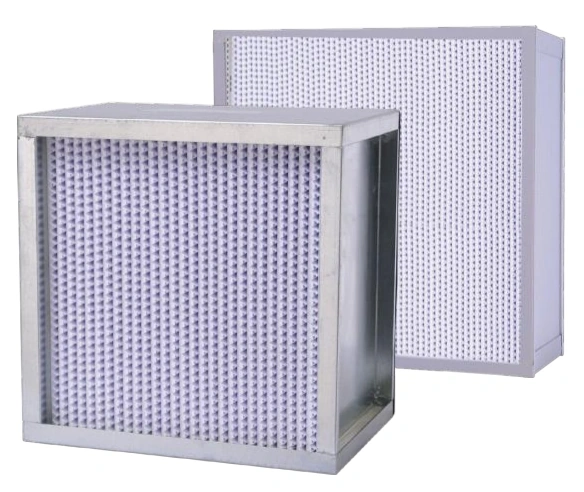
Air Filters
Separator HEPA Filter
| Specification | 320 × 320 | 484 × 484 | 630 × 630 | 968 × 484 | 1260 × 630 |
|---|---|---|---|---|---|
| Series | JNAF-YGK | ||||
| Overall size (W × H × D, mm) | 320 × 320 × 220 | 484 × 484 × 220 | 630 × 630 × 220 | 968 × 484 × 220 | 1260 × 630 × 220 |
| Nominal airflow (m³/h) | 800 | 1700 | 2900 | 3400 | 5700 |
| Grade | H13 | ||||
| Frame / media | Galvanized steel / microglass fibre | ||||
| Separator options | Coated paper / aluminium foil | ||||
| Potting options | Polyurethane / silicone | ||||
| Gasket options | EPDM / silicone | ||||
| Standard temperature / humidity limits | 80°C / 80% RH | ||||
Dimensions and configurations can be customized for your application.
A separator HEPA filter uses corrugated material between the media folds to maintain air passages through a deeper pack. Its selection depends on the housing, duty and service environment as well as the required filtration grade.
Match the deeper pack to the air system
Corrugated separators support the folds and maintain passages through the media pack. This construction creates a deeper filter assembly than a shallow mini-pleat panel. It can suit compatible air-handling or final-filtration housings where the required depth and access are available.
The deeper frame changes more than the space occupied during operation. It also affects the clearance required for removal, the supporting rails and the route through the service opening. Check these details before substituting it for another filter style.
Define the operating environment before choosing materials
The frame, separator, potting compound and gasket are a combined material selection. Heat, humidity and cleaning exposure can affect them differently. A suitable metal frame does not establish that every other component is suitable for the same conditions.
Where elevated temperatures are involved, describe continuous operation, peak exposure and any heating or cooling cycle. Select a complete construction for those conditions rather than applying a high-temperature description to a standard filter.
Keep moisture conditions explicit
Describe whether the filter sees ordinary humid air, condensation or liquid carryover. These are different duties. Address upstream sources of water or mist where necessary instead of expecting the final particulate filter to act as a general-purpose moisture separator.
Consider the complete housing resistance
The fan must overcome the filter and the rest of the air path. Review the design flow, housing transitions and pressure allowance together. Selecting a nominal flow capacity without considering the fan and duct system can leave the installation unable to deliver its intended air quantity.
Maintain upstream filters where provided and monitor the system under its actual operating conditions. The suitable replacement point depends on pressure availability, filter condition and process requirements. An unchanged airflow indication alone does not establish that a damaged or poorly seated filter remains acceptable.
Make the service operation manageable
Support the frame
Plan how the filter will be lifted and guided into the housing. Avoid using the media folds or exposed separator edges as handholds.
Check the seal
Match the gasket profile and position to the retaining arrangement. Inspect seating surfaces and fixings instead of compensating for a poor fit with excessive force.
Plan removal
Leave room for the full-depth filter and the handling equipment. Choose the service procedure around the material collected during use and the facility's maintenance requirements.
Provide the housing dimensions, airflow, operating temperature and humidity, and required seal arrangement. Filter size and material configuration can be customized to the application. Discuss a separator-filter configuration.